Side column configuration for overhead roll-up door assemblies

a technology for side columns and assemblies, which is applied in the direction of door/window protective devices, shutters/movable grilles, and door panels. it can solve the problems of reducing the wind load and affecting the wind resistance of the door. it can reduce the gap size, increase the wind load resistance, and facilitate the disengagement of the door panel

Active Publication Date: 2015-11-17
RYTEC CORP
View PDF24 Cites 11 Cited by
  • Summary
  • Abstract
  • Description
  • Claims
  • Application Information

AI Technical Summary

Benefits of technology

[0014]According to still another aspect of the invention each side column includes a fixed portion. The fixed portion of the side column includes a first portion which attaches to the arm and a second portion which may support the header of the door assembly. The second portion may additionally be configured to form a boundary of a gap with the arm through which the door panel extends from the opening to the interior of the side column, and through which the edge of the door panel must pass in order for the door panel to disengage from the side column if the panel is impacted by a vehicle or an object. Movement of the arm in the first direction may reduce the size of the gap and pinch the door panel, increasing the wind load resistance for example, and preventing the door panel from escaping the side column. Movement of the arm in the second direction may allow the door panel to escape the side columns. In order to better facilitate disengagement of the door panel from the side column, moment forces above the second threshold may also cause movement in the second direction of a portion of the first portion of the fixed structure.
[0015]According to another aspect of the invention, the arm and first portion of the fixed structure may include slots, through holes, apertures or similar structures through which one or more fasteners may fasten the arm to the fixed body. The length of the arm, or the distance that the arm extends towards the center of the door or opening, may be adjusted by aligning different slots or apertures in the arm with different slots or apertures in the fixed structure. Adjusting the length of the arm and the portion of the arm which overlaps with the first portion of the fixed structure will increase or decrease the ease with which the arm will move in the second direction. For example, a shorter arm with greater overlap will move in the second direction less easily than a longer arm with less overlap.

Problems solved by technology

However, using a thickened edge may prevent the door panel and associated edges from disengaging from the side column if the door panel is impacted by an object or vehicle.
This, in turn, often leads to damage to one or more of the side columns, door panel, door components, surrounding building structures, the vehicle, and / or any objects located near the door.
However, such a configuration does not provide for any enhanced wind resistance as the wind load increases, and indeed may allow the door panel to escape under substantial wind loads if the spring compresses.
As is known in the art, springs may also break and wear out, lowering the wind locking capabilities of the side column and door panel.
However, such side columns do not provide any enhancement of the wind resistance of the door as the wind load is increased, inasmuch as the side columns are not designed to move in a manner which prevents the door panel from escaping the side columns.

Method used


Image

  • Side column configuration for overhead roll-up door assemblies
  • Side column configuration for overhead roll-up door assemblies
  • Side column configuration for overhead roll-up door assemblies

Examples


Embodiment Construction

[0032]While the present invention is susceptible of embodiment in many different forms, there is shown in the drawings and will herein be described in detail, preferred embodiments of the invention with the understanding that the present disclosure is to be considered as an exemplification of the principles of the invention and is not intended to limit the broad aspect of the invention to the embodiments illustrated.

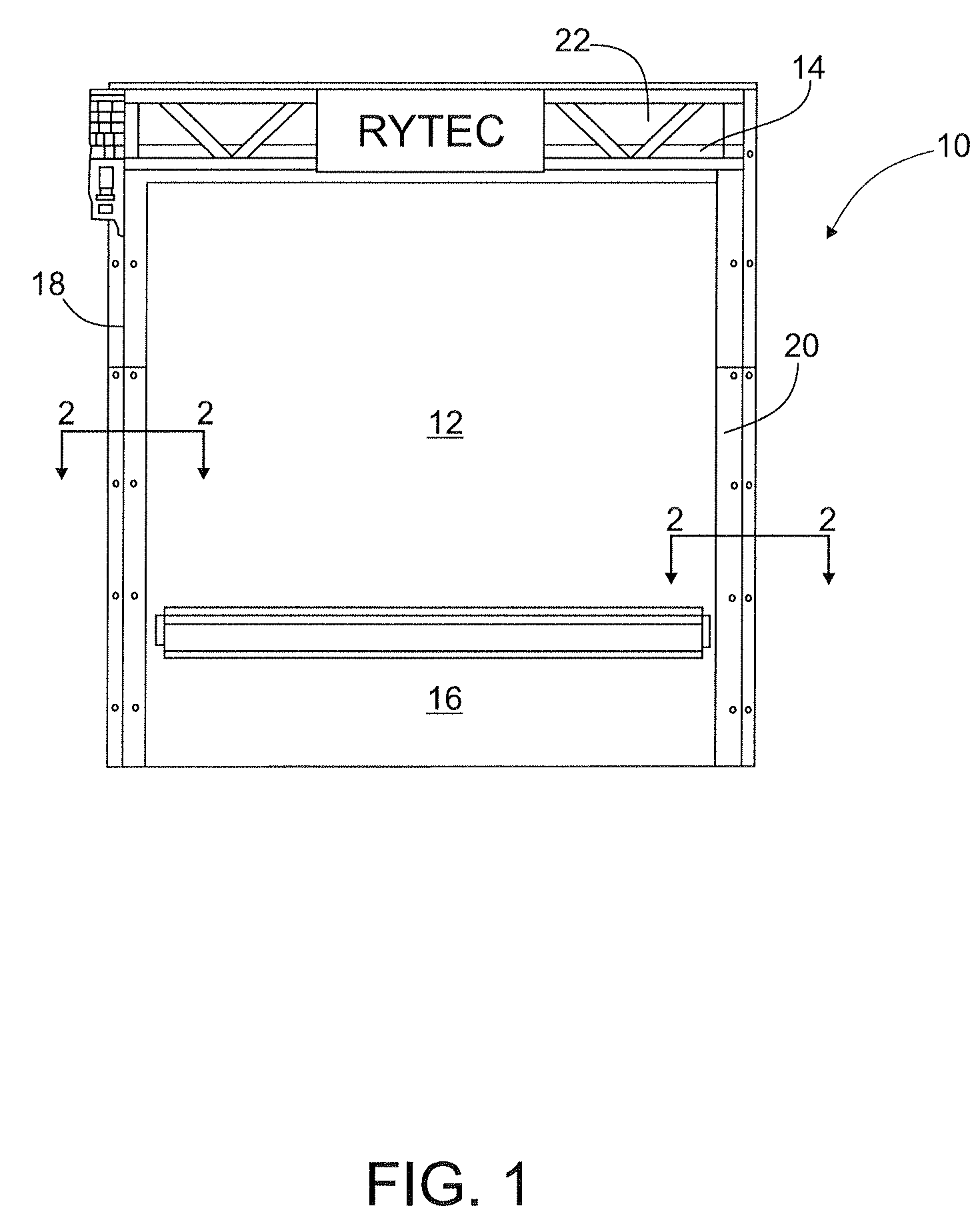
[0033]FIG. 1 shows an overhead roll-up door assembly as contemplated by the present invention. Door assembly 10 includes a flexible roll-up door panel 12, that is vertically moved by being wound and unwound from drum or shaft 14 to permit and prohibit access to opening 16. The door panel includes first and second faces, and first and second opposed vertical sides located on opposite sides of the opening, each vertical side having a marginal edge. In order to guide the vertical movement of the door panel, side columns 18, 20 are located proximate opposing sides of the ope...


PUM


Abstract

An overhead roll-up door assembly for a vertically moving door to permit and prohibit access to an opening in a wall, the door assembly having a flexible door panel and side columns located proximate opposite sides of the opening. The side columns each include an arm configured to engage the door panel as the door panel moves vertically, the arms being configured to move in a first direction in response to a first threshold moment being applied to the arms by the door panel wherein movement of each arm in the first direction prevents the door panel from escaping the side columns. The arms may be further configured to move in a second direction in response to a second threshold moment being applied on the arms by the door panel in a substantially vertical direction perpendicular to and away from the door panel.

Description

RELATED APPLICATIONS[0001]This application claims priority to U.S. Provisional Application Ser. No. 61 / 466,913 entitled “A DOOR ASSEMBLY HAVING A FLEXIBLE PANEL WHICH IS WOUND AND UNWOUND UPON A DRUM AND HAVING SIDE SUPPORT AND GUIDE COLUMNS WITH CAM STRUCTURES TO IMPEDE BLOW OUT DUE TO WIND LOAD” filed Mar. 23, 2011; U.S. Provisional Application Ser. No. 61 / 465,698 entitled “A DOOR ASSEMBLY HAVING A FLEXIBLE PANEL WHICH IS WOUND AND UNWOUND UPON A DRUM AND HAVING SIDE SUPPORT AND GUIDE COLUMNS WITH CAM STRUCTURES TO IMPEDE BLOW OUT DUE TO WIND LOAD” filed Mar. 23, 2011; U.S. Provisional Application Ser. No. 61 / 466,922 entitled “SEGMENTED WIND LOCK CONFIGURATION FOR OVERHEAD ROLL-UP DOORS AND METHOD OF USING SAME” filed Mar. 23, 2011; and, U.S. Provisional Application Ser. No. 61 / 534,356 entitled “CONTINUOUS WIND LOCK CONFIGURATION FOR OVERHEAD ROLL-UP DOOR” filed Sep. 13, 2011—the contents of all of which are fully incorporated herein by reference.FIELD OF THE INVENTION[0002]The pr...

Claims


Application Information

Patent Timeline
Patent Type & Authority Patents(United States)
IPC IPC(8): E06B9/56E06B9/58E06B9/13E06B1/52E06B3/80
CPCE06B9/581E06B9/13E06B9/58E06B1/522E06B3/80E06B2009/585
Inventor DRIFKA, BRIAN NORBERTGONTARSKI, CHRISTOPHER
Owner RYTEC CORP
Why Eureka
Try Eureka