Anti-zipper puller sliding device

a technology of sliding device and zipper, which is applied in the direction of padlocks, building locks, constructions, etc., can solve the problems of significant security threat, luggage zipper can be easily breached, and luggage zipper breaching

Active Publication Date: 2015-11-24
SUN LOCK COMPANY LIMITED -THE-
View PDF14 Cites 8 Cited by
  • Summary
  • Abstract
  • Description
  • Claims
  • Application Information

AI Technical Summary

Benefits of technology

[0008]The present invention is designed to overcome the above noted limitations that are attendant upon the use of conventional luggage locks and, toward this end, it contemplates the provision of a novel an anti-zipper puller sliding device which prevents a breach of a luggage zipper from being concealed by re-zipping the zipper even when a luggage lock is affixed to the zipper pullers.
[0009]The anti-zipper sliding device may include at least one body; a gripping surface affixed onto the body a fastener to removably attach the body and the gripping surface onto a piece of luggage having a zipper with a zipper track and a zipper puller so as to prevent the device from moving relative to the luggage; and means for attaching the device to a padlock so as to lock the zipper puller to the device thereby preventing the zipper from being re-zipped after a zipper breach.
[0010]Accordingly, it is an object of the present invention to provide an anti-zipper puller sliding device that restricts an unauthorized person from being able to slide zipper pullers of a zipper track back and forth to seal a breached zipper track.
[0011]It is another object of the present invention to provide a mechanism so that a zipper breach is evident since the luggage zipper cannot be re-zipped, and leaving the luggage will therefore be left with a gap (i.e., un-zipped), which will alert everyone that the luggage has been breached.
[0015]In accordance with the exemplary embodiment of the present invention, the first body portion and the second body portion are configured for attachment to a piece of luggage having a zipper track with at least one zipper so as to prevent movement of the anti-zipper sliding device along the zipper track of the luggage, and the cover is further configured to be secured to the first body portion by a locking mechanism when the cover covers at least a part of the first body portion.
[0032]In accordance with the exemplary embodiment of the present invention, the second body portion may include a protection ring extending from a surface of the second body opposite a surface from which the at least one gripping member extends from, and the protection ring is configured to protect the fastener from being released from the ant-zipper sliding device when the anti-zipper sliding device is in the clamped mode.

Problems solved by technology

However, a luggage zipper can be easily breached by use of a pointed article, such as a ball point pen.
Such breaching of luggage where no evidence is left that the luggage was breached, is a significant security threat since items could be placed in a piece of luggage without knowledge of the owner of the luggage, even though the luggage zipper is locked with a TSA approved luggage lock.
This means that an unauthorized person can steal items from a locked piece of luggage within seconds; yet, the lock is not being tampered with nor is there evidence of the zipper breach.
This is a serious problem which can make the owner of the luggage feel unsafe, especially, when there are valuable items placed in luggage.
Such theft of items would typically not be noticed until the luggage lock is unlocked and the luggage opened.
Furthermore, such a zipper breach could be used by a terrorist or smuggler to insert some type of contraband into the luggage.
Therefore, there is a need to restrict the movement of the zippers so that the gap of the zipper cannot be resealed once there has been an unauthorized zipper breach.

Method used


Image

  • Anti-zipper puller sliding device
  • Anti-zipper puller sliding device
  • Anti-zipper puller sliding device

Examples


Embodiment Construction

[0047]The present invention now will be described more fully hereinafter with reference to the accompanying figures, in which exemplary embodiments of the invention are shown. The invention may, however, be embodied in many different forms and should not be construed as limited to the embodiments set forth herein. Like reference numerals refer to like elements throughout.

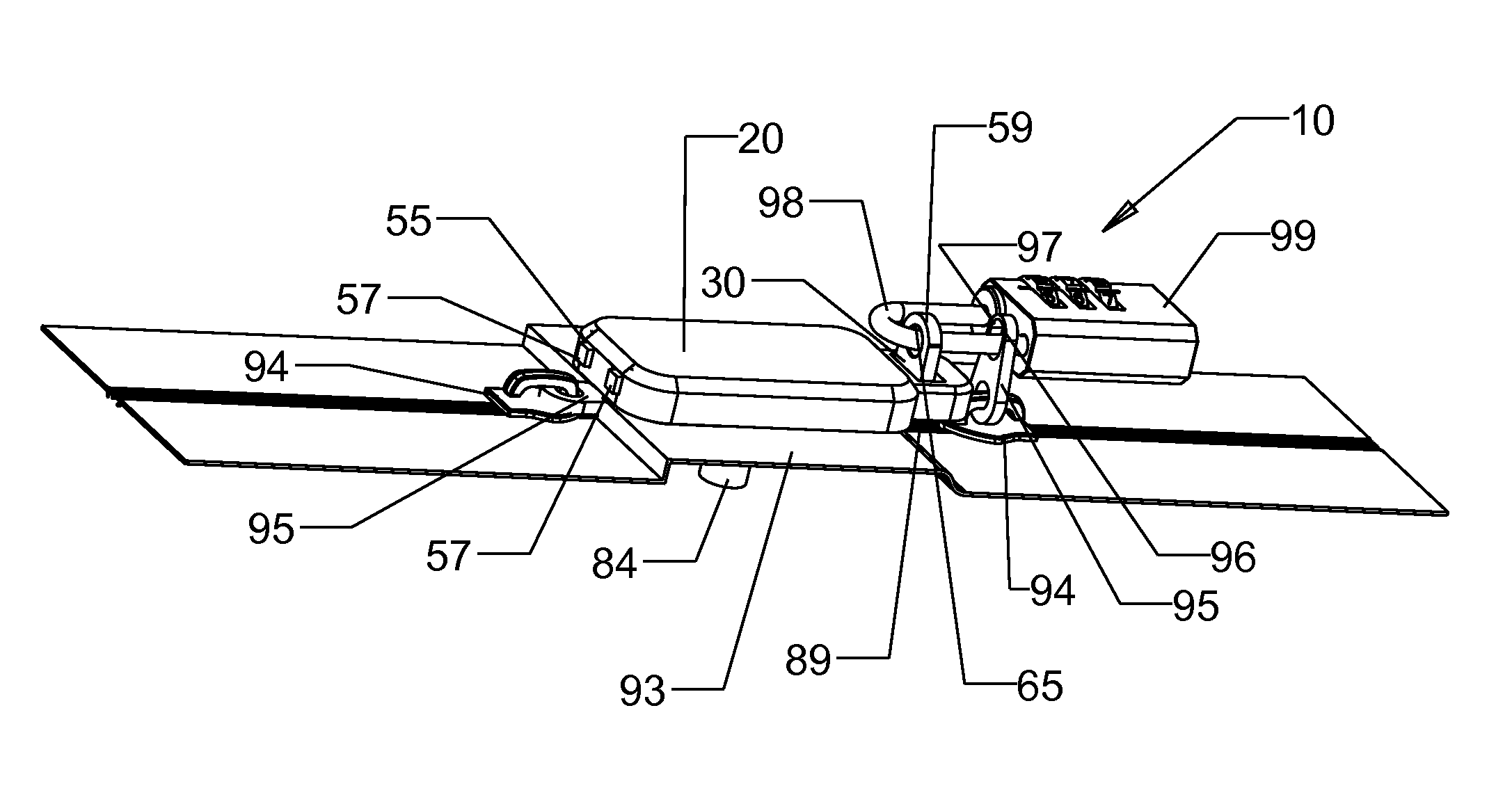
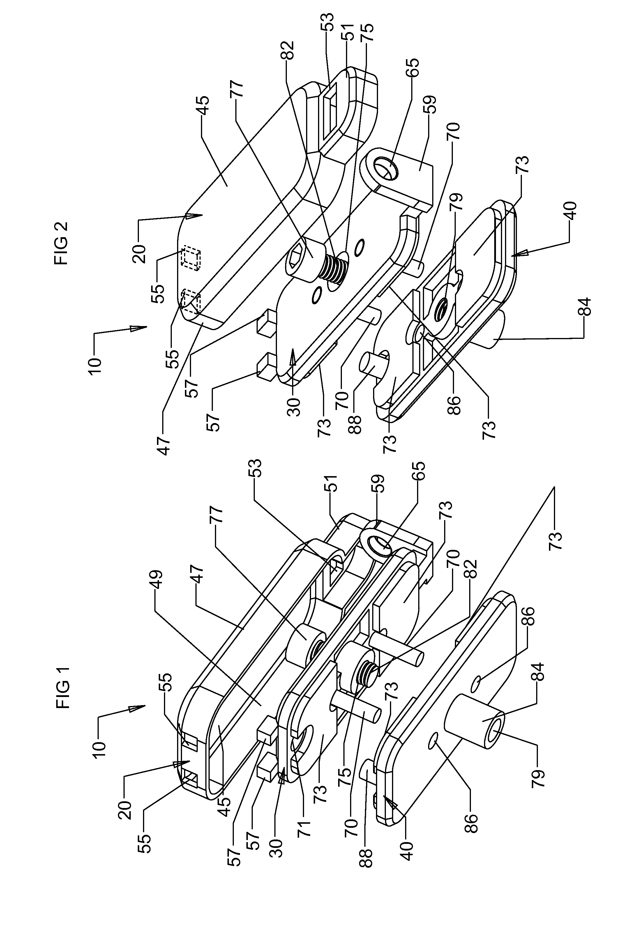
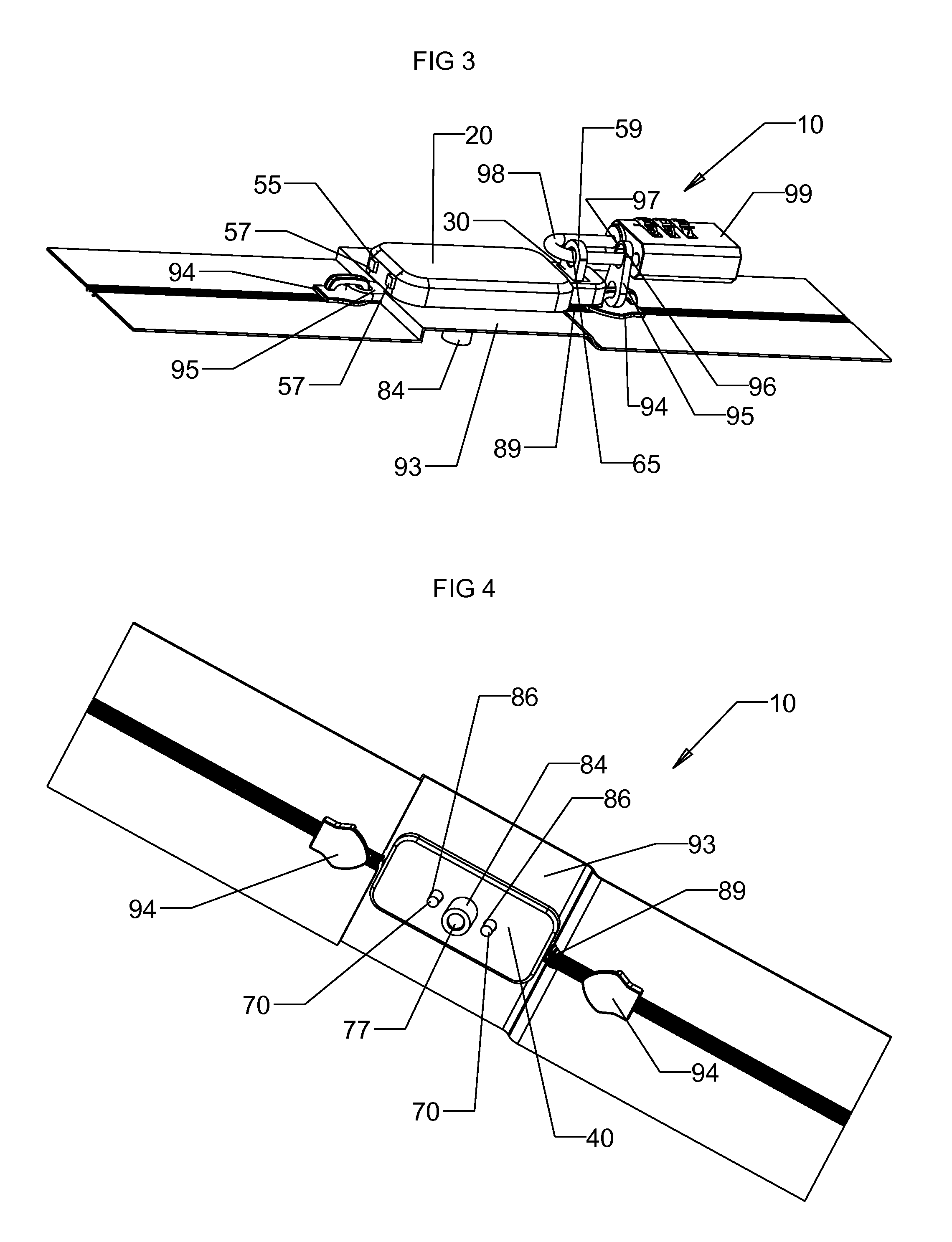
[0048]Referring now to FIGS. 1-2, in which an exemplary embodiment of an anti-zipper sliding device, generally indicated by reference numeral 10, according to the present invention is shown. The anti-zipper sliding device 10 includes a cover 20, an upper body 30 and a lower body 40. The upper body 30 and the lower body 40 are configured for releaseable engagement with each other, and the cover 20 is dimensioned to at least partially cover the upper body 30. It is understood that the use of the terms “upper” and “lower” to refer to the upper body 30 and the lower 40 are merely used to identify the body portions, and ...


PUM


Abstract

The present invention is directed to embodiments of an anti-zipper sliding device that may include at least one body, a gripping surface affixed onto the body, a fastener to removably attach the body and the gripping surface onto a piece of luggage having a zipper with a zipper track and a zipper puller so as to prevent the anti-zipper sliding device from moving along the zipper track of the luggage. The anti-zipper sliding device may also include at least one locking mechanism or be configured for engagement with at least one locking mechanism in order to lock at least one zipper puller to the anti-zipper sliding device in order to prevent the zipper from being re-zipped after a zipper breach.

Description

CROSS-REFERENCE TO RELATED APPLICATIONS[0001]This application claims priority to U.S. Provisional Appl. No. 61 / 696,556 filed Sep. 4, 2012, which is hereby incorporated by reference in its entirety.BACKGROUND OF THE INVENTION[0002]1. Field of the Invention[0003]The present invention relates to a device for making a zipper breach evident, and more particularly a device for making a zipper breach in luggage evident.[0004]2. Description of Related Art[0005]There are many types of baggage locks which are used to lock together the zipper pullers on luggage, thereby preventing the zipper from being opened by unauthorized personnel. Many of these locks are approved by the Transportation Security Administration (TSA) and have means for allowing a master key to open the locks by TSA approved personnel.[0006]However, a luggage zipper can be easily breached by use of a pointed article, such as a ball point pen. The term “zipper breach” in this application means the use of a sharp pointed item, ...

Claims


Application Information

Patent Timeline
Patent Type & Authority Patents(United States)
IPC IPC(8): E05B67/38A45C13/18A45C13/10A44B19/30A45C5/00E05B65/52
CPCE05B65/52A44B19/30A45C5/00A45C13/103A45C13/18Y10T70/5053E05B67/38
Inventor LAI, KARL
Owner SUN LOCK COMPANY LIMITED -THE-
Why Eureka
Try Eureka