
Transmission method and apparatus for non-periodic sounding reference signal(SRS)

a reference signal and transmission method technology, applied in the field of communication technology, can solve the problems of increasing the resource consumption of pdcch, occupying much more physical resources, and occupying more physical resources for periodic srs, so as to reduce signalling consumption, reduce signalling delay, and great sounding bandwidth

Active Publication Date: 2015-11-24
DATANG MOBILE COMM EQUIP CO LTD
View PDF6 Cites 1 Cited by
  • Summary
  • Abstract
  • Description
  • Claims
  • Application Information

AI Technical Summary

Benefits of technology

[0021]Compared with available technology, the embodiments of the present invention have the following advantages:
[0022]Application of the technical solution of the embodiments of the present invention can reduce signalling consumption relying on high-layer semi-static configuration of time-domain resource of non-periodic SRS. On one hand, flexible non-periodic SRS time-domain transmission is allowed for terminal equipment which can send non-periodic SRS in multiple subframes, which is featured by low sounding delay and great sounding bandwidth; on the other hand, flexible timing mode is also permitted for terminal equipment which brings little restriction to scheduling.

Problems solved by technology

Owing to long scheduling periodicity and low scheduling efficiency, periodic SRS often occupies much more physical resources.
Especially in LTE-A (Long Term Evolution Advanced) system, UE (User Apparatus) often requires sending SRS of multiple antennas at the same time, thus resulting in more resource consumption.
Configuration of non-periodic SRS by introducing dedicated DCI format of SRS in present technology will greatly increase resource consumption of PDCCH, even waste PDCCH resource to certain extent due to less configuration bit.
There will be great resource consumption if many users are activated, thus making PDCCH unaffordable.

Method used


Image

  • Transmission method and apparatus for non-periodic sounding reference signal(SRS)
  • Transmission method and apparatus for non-periodic sounding reference signal(SRS)
  • Transmission method and apparatus for non-periodic sounding reference signal(SRS)

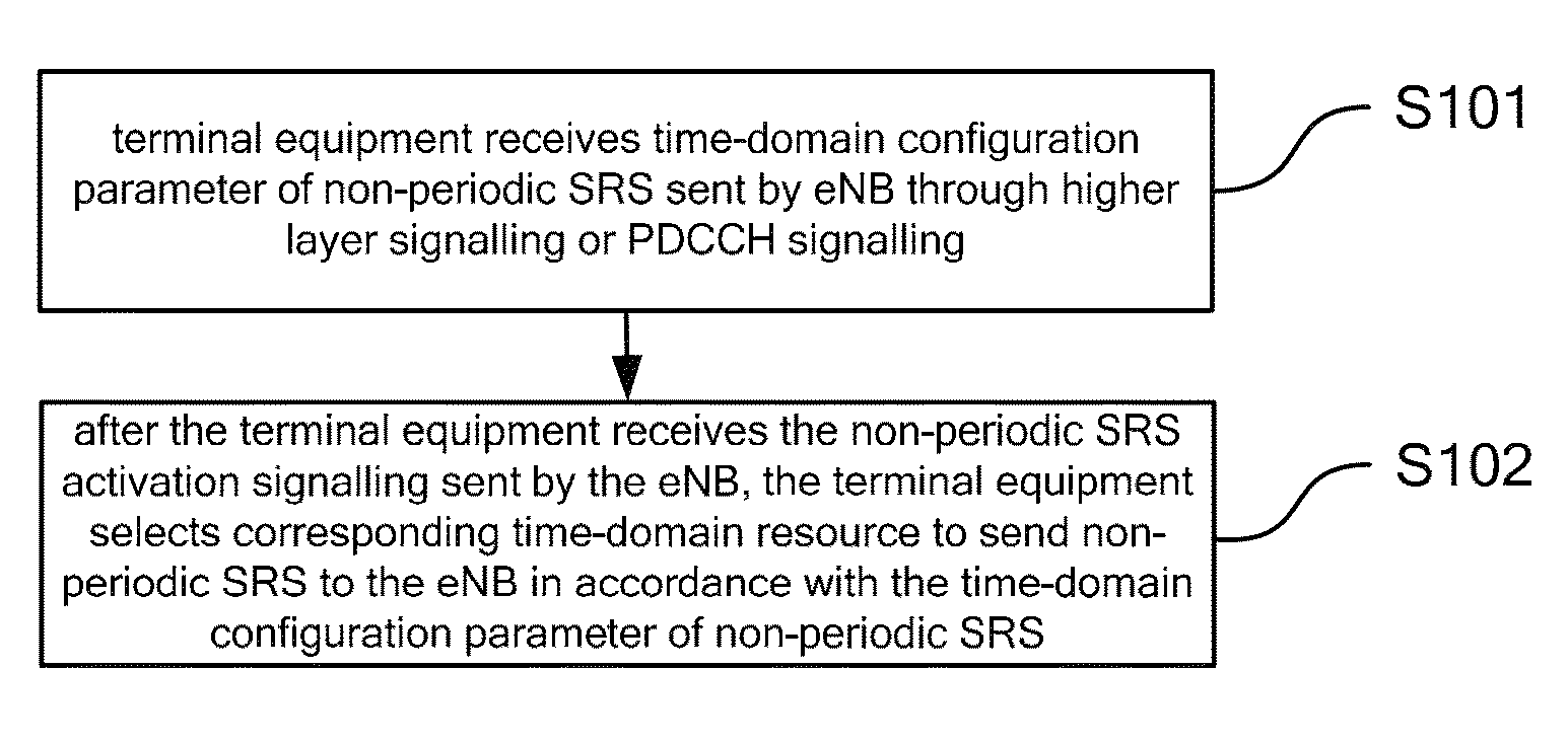
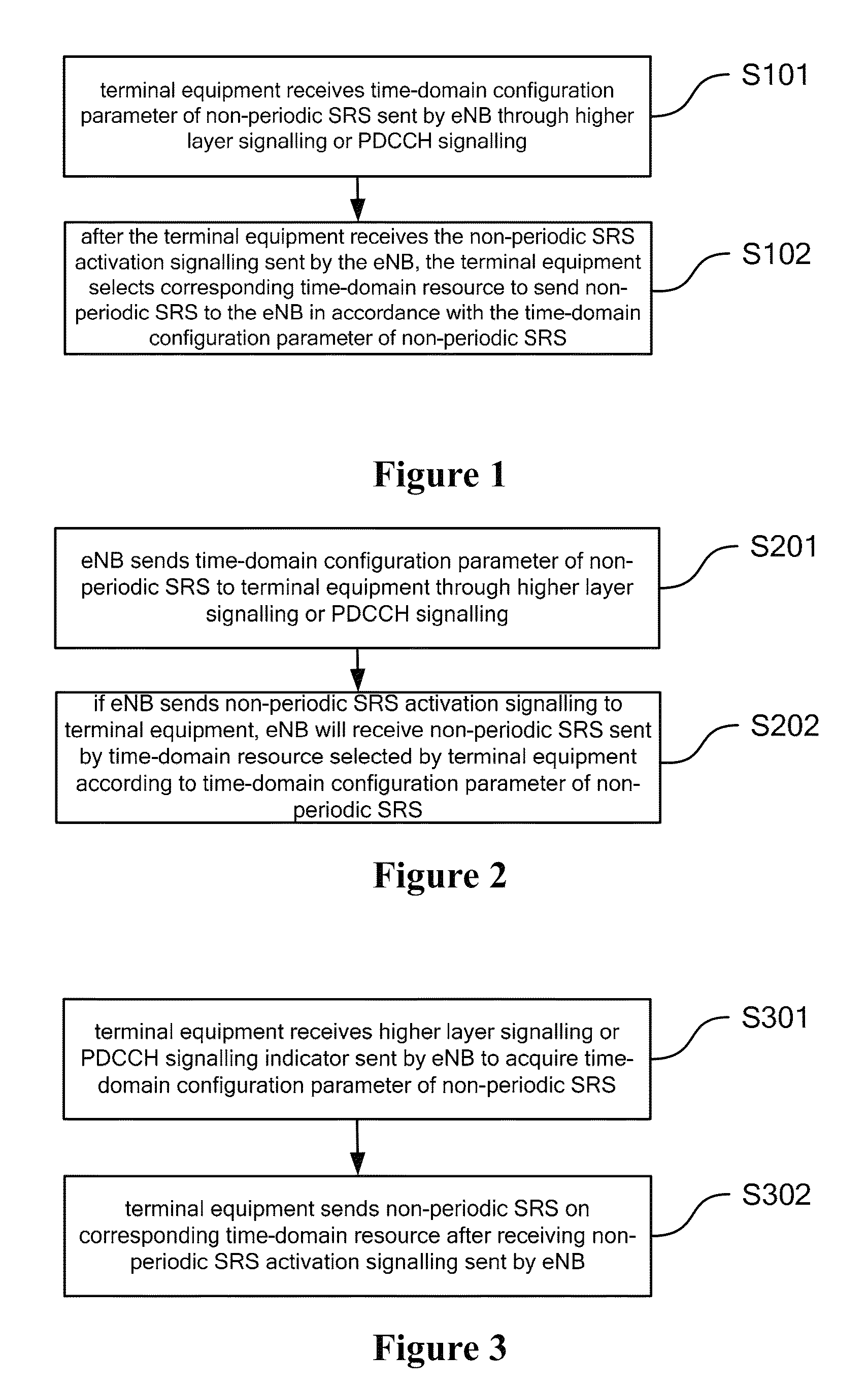
Examples


Embodiment Construction

[0028]In LTE-A system, periodic SRS (Sounding Reference Signal) requires occupying much more physical resources due to the introduction of multiple antenna transmission. To improve SRS resource utilization rate and reduce consumption of SRS resource, non-periodic SRS transmission is introduced in LTE-A system to activate one-off sounding through dynamic scheduling.

[0029]It is necessary to solve the problem on how to conduct time-domain resource scheduling of non-periodic SRS and send non-periodic SRS by terminal equipment after receiving signalling from eNB in right way.

[0030]The embodiments of the present invention provide a transmission method for non-periodic SRS. eNB configures time-domain parameter of non-periodic SRS through higher layer signalling or PDCCH signalling, and terminal equipment conducts SRS transmission based on the configuration, which can reasonably and effectively schedule and transmit time-domain resource of non-periodic SRS.

[0031]To solve the problem existin...


PUM


Abstract

The present invention discloses a transmission method and apparatus for non-periodic SRS. eNB configures time-domain configuration parameter of non-periodic SRS through higher layer signalling or downlink physical control channel signalling; terminal equipment transmits non-periodic SRS in indicated time-domain resource. The application of the technical solution of the embodiments of the present invention can reduce signalling consumption through high layer semi-static configuration of time-domain resource of non-periodic SRS. On one hand, flexible non-periodic SRS time-domain transmission is allowed for terminal equipment which can send non-periodic SRS in multiple subframes, which is featured by low sounding delay and great sounding bandwidth; on the other hand, flexible timing mode is also permitted for terminal equipment which brings little restriction to scheduling.

Description

CROSS REFERENCE TO RELATED APPLICATIONS[0001]This application is the U.S. national stage of international patent application no. PCT / CN2011 / 074186 filed on May 17, 2011, which claims priority to Chinese patent application no. 201010195422.0 entitled “Transmission Method and Apparatus For Non-periodic Sounding Reference Symbol(SRS)” filed in the patent office of the People's Republic of China on May 31, 2010, the disclosures of which are incorporated by reference herein in their entireties.FIELD OF THE INVENTION[0002]The present invention relates to the field of communication technology, in particular to the transmission method and apparatus for non-periodic SRS.BACKGROUND OF THE INVENTION[0003]In current system, uplink channel is detected relying on sounding symbol. eNB can acquire uplink channel information by the way that terminal equipment sends sounding symbol at the last symbol of SRS subframe, so as to schedule and measure resource transmitted through uplink, including measure...

Claims


Application Information

Patent Timeline
Patent Type & Authority Patents(United States)
IPC IPC(8): H04W4/00H04W72/02H04W72/04
CPCH04W72/02H04W72/042H04L5/0051H04L5/0094H04W72/23H04L5/0048
Inventor CHEN, WENHONGTAMRAKAR, RAKESHXIAO, GUOJUN
Owner DATANG MOBILE COMM EQUIP CO LTD
Learn More