Implantable medical lead

a technology of medical leads and electrical leads, applied in the direction of transvascular endocardial electrodes, connections effected by permanent deformation, therapy, etc., can solve the problems of reducing manufacturing, assembly, and overall cost of having significant different system designs and assembly processes, so as to reduce the cost of tooling and manufacturing.

Active Publication Date: 2015-12-01
MICROPORT SORIN CRM (SHANGHAI) CO LTD
View PDF19 Cites 2 Cited by
  • Summary
  • Abstract
  • Description
  • Claims
  • Application Information

AI Technical Summary

Benefits of technology

[0019]One of the advantages of the embodiments disclosed herein is that most of the parts and components of active and passive leads can be shared. As such, while the several parts of the passive lead may be more involved or complicated than other passive lead designs, the commonality between the parts of the active lead and passive lead may reduce the cost of tooling, manufacturing, and assembly for a manufacturer that is manufacturing both active and passive leads. By reducing the differences between the two types of leads, the savings in manufacturing the leads may make up for any costs associated with a more complicated passive lead design.

Problems solved by technology

As a result, the overall cost of having significant different system designs and assembly processes is relatively high and a system having common features or similar or exchangeable components between an active electrical lead and a passive electrical lead may be less expensive and more attractive to consumers.
As such, while the several parts of the passive lead may be more involved or complicated than other passive lead designs, the commonality between the parts of the active lead and passive lead may reduce the cost of tooling, manufacturing, and assembly for a manufacturer that is manufacturing both active and passive leads.

Method used


Image

  • Implantable medical lead
  • Implantable medical lead
  • Implantable medical lead

Examples


Embodiment Construction

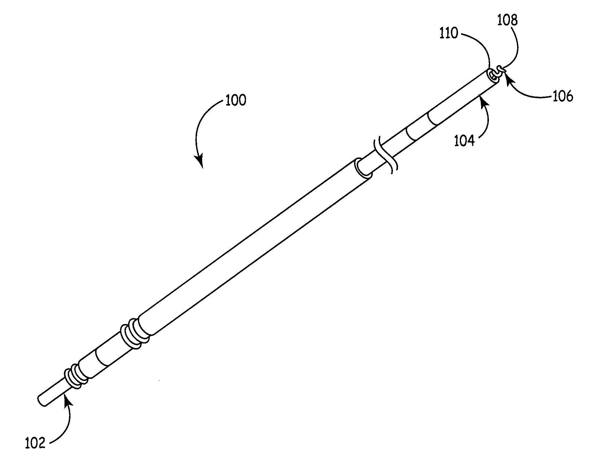
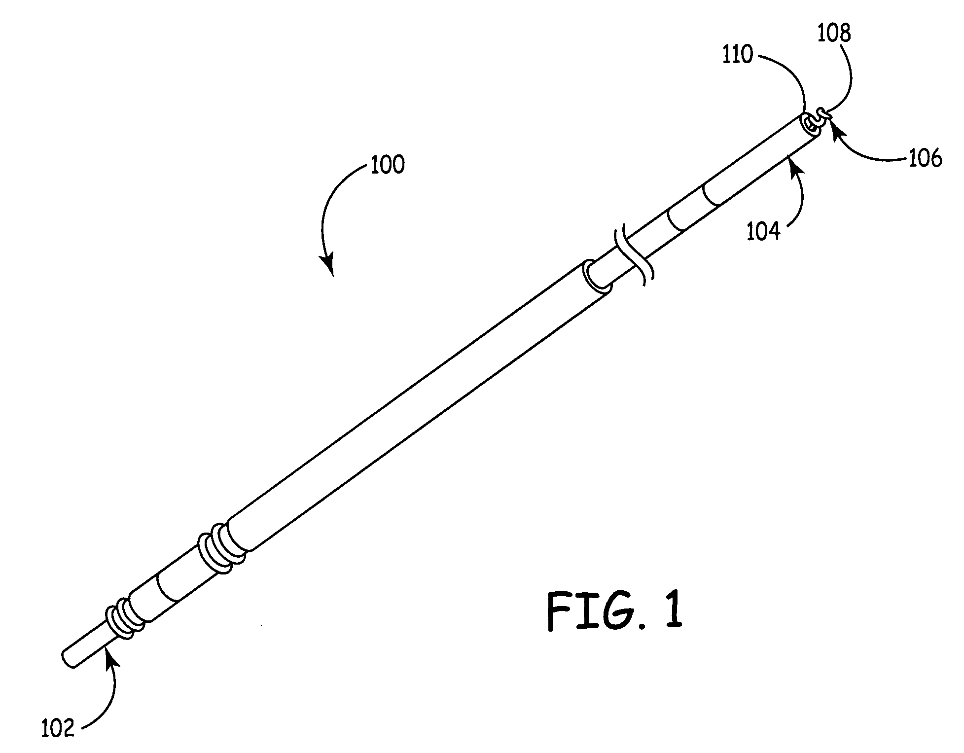
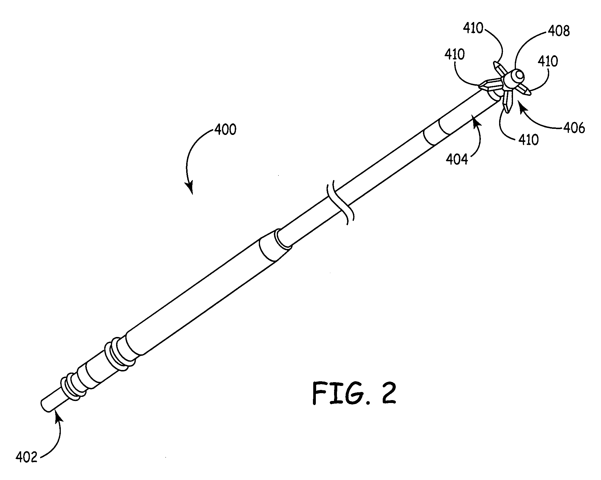
[0033]The present disclosure relates, in one embodiment, to an implantable electrical lead having an active mechanism on a distal end for engaging the heart or other treatment site of a patient. (i.e., active lead) In another embodiment, the present disclosure relates to an implantable electrical lead having a passive mechanism on a distal end. (i.e., passive lead) Each of the active and passive leads may include a system of parts on a proximal end thereof that is primarily adapted to connect to and electrically communicate with a defibrillator, pace maker, or other electrical stimulation device. It is noted that some of the parts may be adapted to insulate between other parts and / or between the proximal end and the electrical stimulation device. In the case of the active lead, a portion of the parts may be particularly adapted to allow actuation and control of the active mechanism on the distal end of the lead while others of the parts may be more generic for use with active or pas...


PUM


Abstract

A proximal end of an implantable lead may include a unitary connector pin having a socket end, a conductor end, and a necked-down portion arranged therebetween, where the conductor end includes a crimp cavity with an inner surface and a proximal end of the conductor is arranged in the crimp cavity, and a pin sleeve sleevably engaging the proximal end of the conductor and crimping the proximal end of the conductor against the inner surface, the proximal end may also include a unitary ring connector having a band portion, a notch portion, and a crimp portion where the crimp portion includes a crimp cavity with an inner surface and a proximal end of the conductor is arranged in the crimp cavity, and a ring sleeve sleevably engaging the proximal end of the conductor and crimping the proximal end of the conductor against the inner surface creating a crimp connection.

Description

[0001]This application is a 35 USC 371 national stage of PCT Patent Application No. PCT / CN2011 / 081808, filed Nov. 4, 2011, entitled “Implantable Medical Lead,” the entire contents of which is hereby incorporated by reference, in its entirety.FIELD OF THE INVENTION[0002]The present disclosure relates generally to implantable electrical leads. More particularly, the present disclosure relates to connection end features of implantable electrical leads where the lead is connected to an associated defibrillator, pacemaker, or other electrical stimulation device. Still more particularly, the present disclosure relates to connection end features of implantable electrical leads having an active mechanism on a treatment end thereof.BACKGROUND OF THE INVENTION[0003]Electrodes are often used to stimulate contraction of the heart. For example, when a patient's heart is functioning with an abnormal rhythm, electrical energy may be applied to the heart via the electrodes to return the heart to a ...

Claims


Application Information

Patent Timeline
Patent Type & Authority Patents(United States)
IPC IPC(8): A61N1/05A61N1/375H01R4/20
CPCA61N1/05A61N1/056A61N1/3752H01R2201/12A61N1/0573H01R4/20
Inventor JANG, GRACE YING YANG
Owner MICROPORT SORIN CRM (SHANGHAI) CO LTD
Why Eureka
Try Eureka