Eureka AIR delivers breakthrough ideas for toughest innovation challenges, trusted by R&D personnel around the world.

Rack-driven auxiliary power steering apparatus

a technology of auxiliary steering and racks, which is applied in the direction of gearing, transportation and packaging, hoisting equipment, etc., can solve the problems of difficult to accurately transmit auxiliary steering power, coupled components to be released, and deterioration of power transmission efficiency, so as to reduce vibration and noise, increase durability, and comfortable steering feeling

Active Publication Date: 2015-12-01
HL MANDO CORP
View PDF16 Cites 4 Cited by
  • Summary
  • Abstract
  • Description
  • Claims
  • Application Information

AI Technical Summary

Benefits of technology

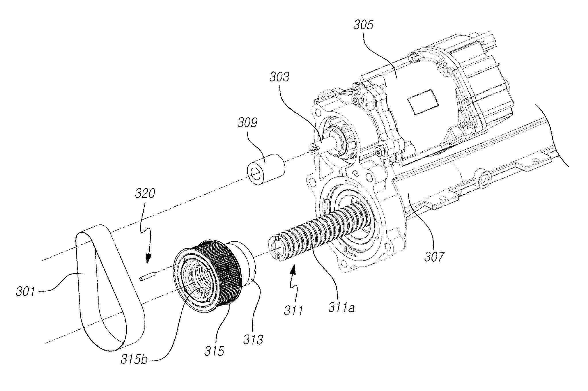
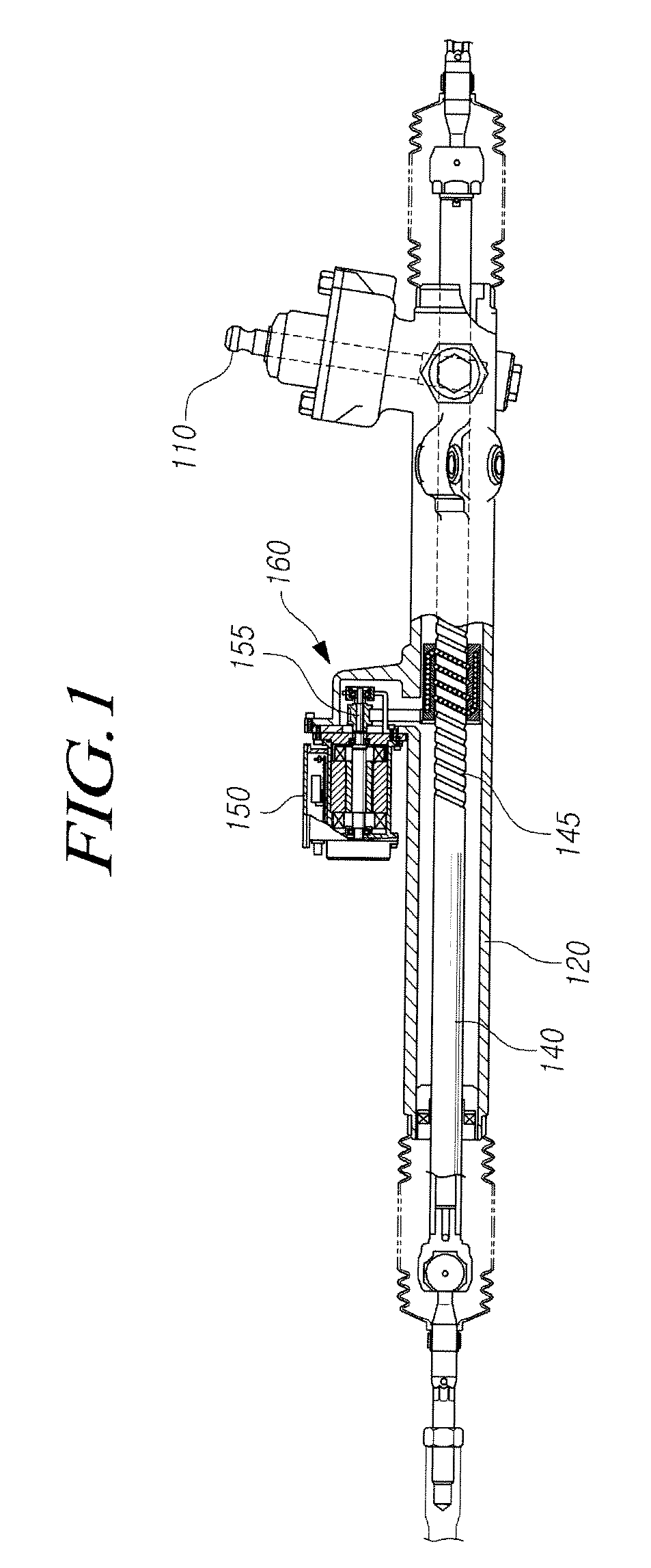
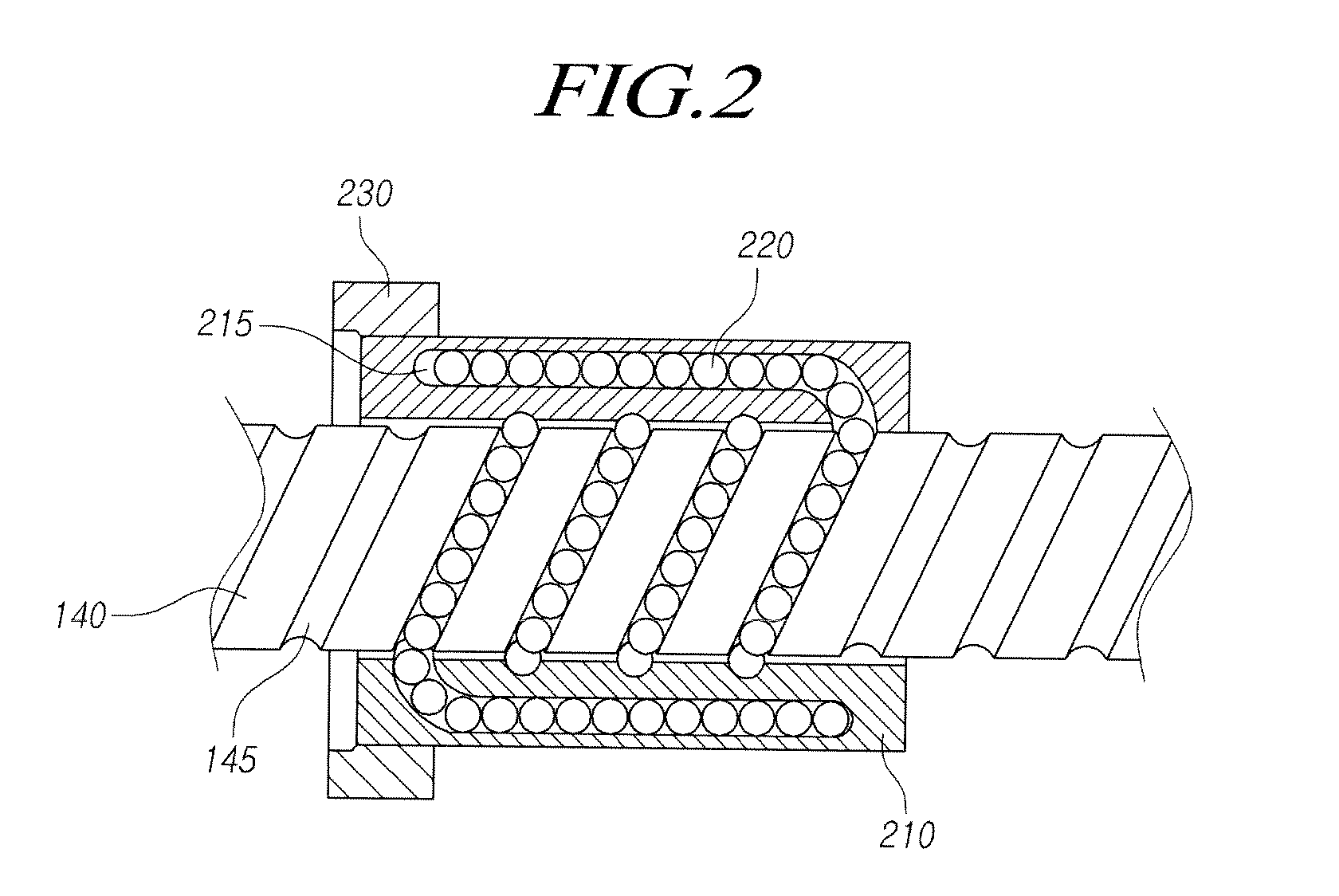
[0017]Accordingly, the present invention has been made to solve the above-mentioned problems occurring in the prior art, and an object of the present invention is to provide a rack-driven auxiliary power steering apparatus which prevents the ball nut and the nut pulley from idling due to a slip thereof and increases durability when the drive belt is operated by driving of a motor, and minimizes vibrations and noise transferred through the rack bar, the ball nut, and the nut pulley when the rack bar is slid while the nut pulley and the ball nut are rotating, thereby providing a comfortable steering feeling to the driver.
[0019]The rack-driven auxiliary power steering apparatus according to the present invention prevents the ball nut and the nut pulley from idling due to a slip thereof and increases durability when the drive belt is operated by driving of a motor, and minimizes vibrations and noise transferred through the rack bar, the ball nut, and the nut pulley when the rack bar is slid while the nut pulley and the ball nut are rotating, thereby providing a comfortable steering feeling to the driver.

Problems solved by technology

However, according to the related art, idling occurs as a slip is generated between the ball nut and the nut pulley, deteriorating power transmission efficiency and making it difficult to accurately transmit an auxiliary steering power.
Further, noise and vibrations are generated in the rack bar, the ball nut, the nut pulley, the bearing, and the rack housing when the rack bar is slid while the ball nut is rotated, which noise and vibrations are transferred to other components, causing the coupled components to be released.
In addition, the transferred noise and vibrations are transferred to the driver together with vibrations and noise of other parts, deteriorating a steering feeling of the driver.

Method used


Image

  • Rack-driven auxiliary power steering apparatus
  • Rack-driven auxiliary power steering apparatus
  • Rack-driven auxiliary power steering apparatus

Examples


Embodiment Construction

[0027]Hereinafter, exemplary embodiments of the present invention will be described with reference to the accompanying drawings. In the following description, the same elements will be designated by the same reference numerals although they are shown in different drawings. Further, in the following description of the present invention, a detailed description of known functions and configurations incorporated herein will be omitted when it may make the subject matter of the present invention rather unclear.

[0028]In addition, terms, such as first, second, A, B, (a), (b) or the like may be used herein when describing components of the present invention. Each of these terminologies is not used to define an essence, order or sequence of a corresponding component but used merely to distinguish the corresponding component from other component(s). It should be noted that if it is described in the specification that one component is “connected,”“coupled” or “joined” to another component, a t...


PUM


Abstract

A rack-driven auxiliary power steering apparatus prevents a ball nut and a nut pulley from idling due to a slip thereof and increases durability when the drive belt is operated by driving of a motor, and minimizes vibrations and noise transferred through the rack bar, the ball nut, and the nut pulley when the rack bar is slid while the nut pulley and the ball nut are rotating, thereby providing a comfortable steering feeling to the driver.

Description

CROSS-REFERENCE TO RELATED APPLICATION[0001]This application claims priority from and the benefit under 35 U.S.C. §119(a) of Korean Patent Application No. 10-2011-0120352, filed on Nov. 17, 2011, which is hereby incorporated by reference for all purposes as if fully set forth herein.BACKGROUND OF THE INVENTION[0002]1. Field of the Invention[0003]The present invention relates to a rack-driven auxiliary power steering apparatus, and more particularly to a rack-driven auxiliary power steering apparatus which prevents a ball nut and a nut pulley from idling due to a slip thereof and increases durability when the drive belt is operated by driving of a motor, and minimizes vibrations and noise transferred through the rack bar, the ball nut, and the nut pulley when the rack bar is slid while the nut pulley and the ball nut are rotating, thereby providing a comfortable steering feeling to the driver.[0004]2. Description of the Prior Art[0005]Hydraulic power steering apparatuses using a hydr...

Claims


Application Information

Patent Timeline
Patent Type & Authority Patents(United States)
IPC IPC(8): B62D5/04F16H25/20F16H25/24F16H55/36
CPCB62D5/0448B62D5/0421B62D5/0424F16H25/20B62D5/0472F16H2055/366F16H25/24B62D3/02B62D3/12
Inventor JUNG, DAE HEEBHAE, HONG YONG
Owner HL MANDO CORP
Why Eureka
Eureka Blog
Learn More