Waveguide power sensor structures free of optical coherence effects in a HAMR drive

a waveguide power sensor and optical coherence effect technology, applied in the field of data storage systems, can solve the problems of fluctuation of optical power of laser diodes (ld), data stored within magnetic bits may not be thermally stable, and may not always be practical when lowering the temperatur

Active Publication Date: 2015-12-01
WESTERN DIGITAL TECH INC
View PDF12 Cites 1 Cited by
  • Summary
  • Abstract
  • Description
  • Claims
  • Application Information

AI Technical Summary

Problems solved by technology

Although grain size can be reduced further, the data stored within the magnetic bits may not be thermally stable.
Lowering the temperature may not always be practical when designing hard disk drives for commercial and consumer use.
During writing operations, optical power from a laser diode (LD) may fluctuate due to mode hopping, temperature drift, and LD aging.

Method used


Image

  • Waveguide power sensor structures free of optical coherence effects in a HAMR drive
  • Waveguide power sensor structures free of optical coherence effects in a HAMR drive
  • Waveguide power sensor structures free of optical coherence effects in a HAMR drive

Examples


Embodiment Construction

[0017]In the following, reference is made to embodiments. However, it should be understood that the invention is not limited to specific described embodiments. Instead, any combination of the following features and elements, whether related to different embodiments or not, is contemplated to implement and practice the invention. Furthermore, although embodiments of the invention may achieve advantages over other possible solutions and / or over the prior art, whether or not a particular advantage is achieved by a given embodiment is not limiting of the invention. Thus, the following aspects, features, embodiments and advantages are merely illustrative and are not considered elements or limitations of the appended claims except where explicitly recited in a claim(s). Likewise, reference to “the invention” shall not be construed as a generalization of any inventive subject matter disclosed herein and shall not be considered to be an element or limitation of the appended claims except wh...


PUM

PropertyMeasurementUnit
lengthaaaaaaaaaa
lengthaaaaaaaaaa
shapeaaaaaaaaaa

Abstract

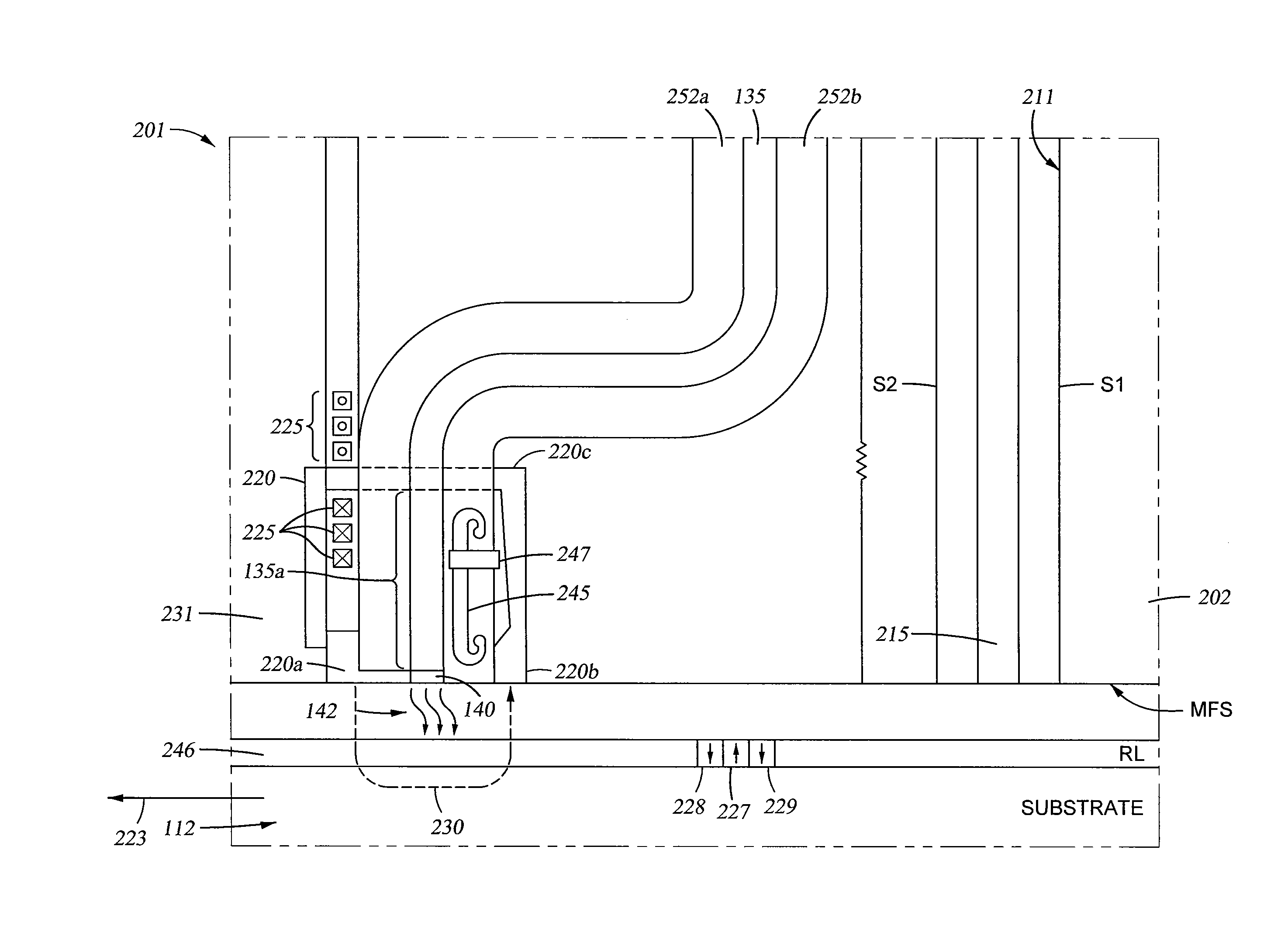
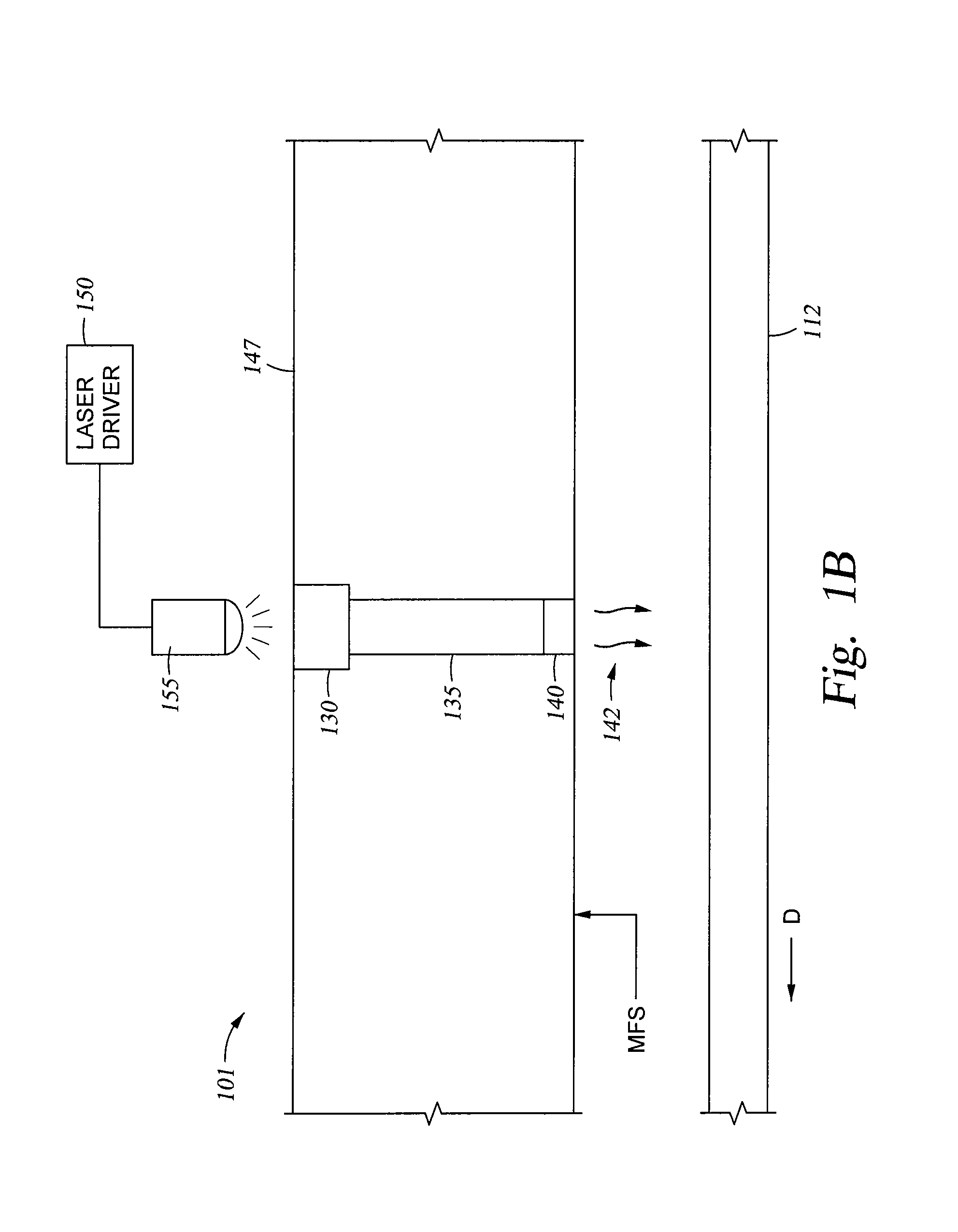
Embodiments disclosed herein generally relate to a HAMR device for use in a magnetic reading system. The HAMR device has a primary waveguide extending from a media facing surface to a surface opposite the media facing surface. In one embodiment, the HAMR head has a secondary waveguide having a first and second end positioned within the HAMR head. The secondary waveguide is positioned near the primary waveguide, and the first and second ends of the secondary waveguide are non-reflecting. A thermal sensor is coupled to the secondary waveguide, and responds only to optical power fluctuations in the primary waveguide. In another embodiment, the HAMR head has a second thermal sensor rather than a secondary waveguide. The first thermal sensor and the second thermal sensor are coupled together to act as one optical power sensor and are disposed on the primary waveguide.

Description

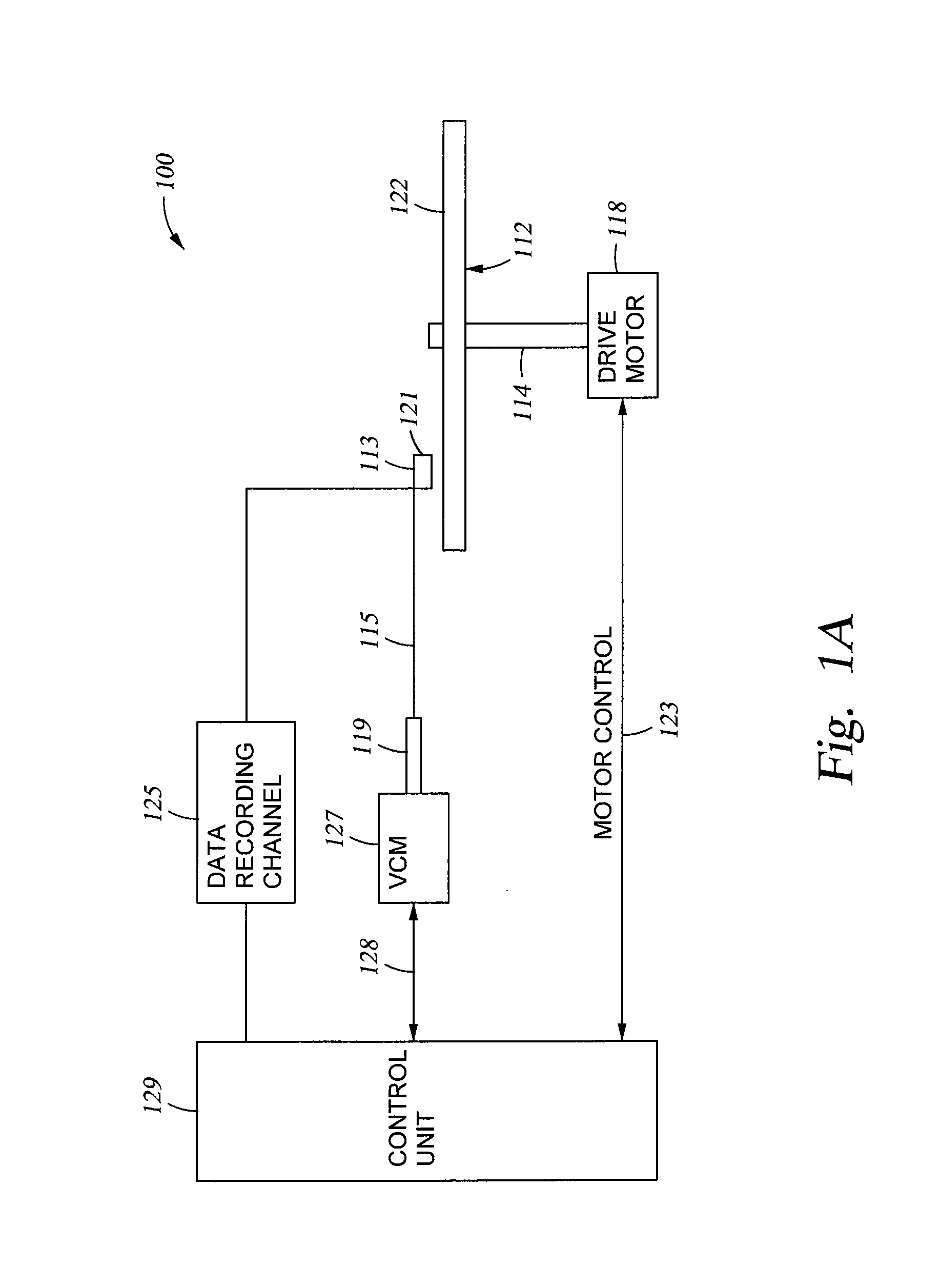
BACKGROUND OF THE INVENTION[0001]1. Field of the Invention[0002]Embodiments disclosed herein generally relate to data storage systems, and more particularly, to thermally assisted recording devices.[0003]2. Description of the Related Art[0004]Higher storage bit densities in magnetic media used in disk drives have reduced the size (volume) of magnetic bits to the point where the magnetic bit dimensions are limited by the grain size of the magnetic material. Although grain size can be reduced further, the data stored within the magnetic bits may not be thermally stable. That is, random thermal fluctuations at ambient temperatures may be sufficient to erase data. This state is described as the superparamagnetic limit, which determines the maximum theoretical storage density for a given magnetic media. This limit may be raised by increasing the coercivity of the magnetic media or by lowering the temperature. Lowering the temperature may not always be practical when designing hard disk d...

Claims


Application Information

Patent Timeline
Patent Type & Authority Patents(United States)
IPC IPC(8): G11B5/00G11B5/60G11B5/48
CPCG11B5/4866G11B5/6088G11B2005/0021G11B5/314
Inventor KIM, SEHEONMATSUMOTO, TAKUYAREN, SHENSTIPE, BARRY C.
Owner WESTERN DIGITAL TECH INC
Why Eureka
Try Eureka