Fixed type constant-velocity universal joint

a constant-velocity, universal joint technology, applied in the direction of yielding couplings, couplings, mechanical devices, etc., can solve the problems of reducing heat generation, reducing torque loss, etc., to achieve excellent durability, reduce torque loss, and enhance efficiency

Active Publication Date: 2015-12-08
NTN CORP
View PDF10 Cites 2 Cited by
  • Summary
  • Abstract
  • Description
  • Claims
  • Application Information

AI Technical Summary

Benefits of technology

[0026]According to one embodiment of the present invention, it is possible to attain a compact fixed type constant velocity universal joint that is suppressed in torque loss and heat generation, enhanced in efficiency, excellent in durability, and is capable of forming high operating angles.

Problems solved by technology

Thus, this structure leads to restriction on achieving even higher efficiency and less heat generation.

Method used


Image

  • Fixed type constant-velocity universal joint
  • Fixed type constant-velocity universal joint
  • Fixed type constant-velocity universal joint

Examples


Embodiment Construction

[0052]Embodiments of the present invention are described with reference to the drawings.

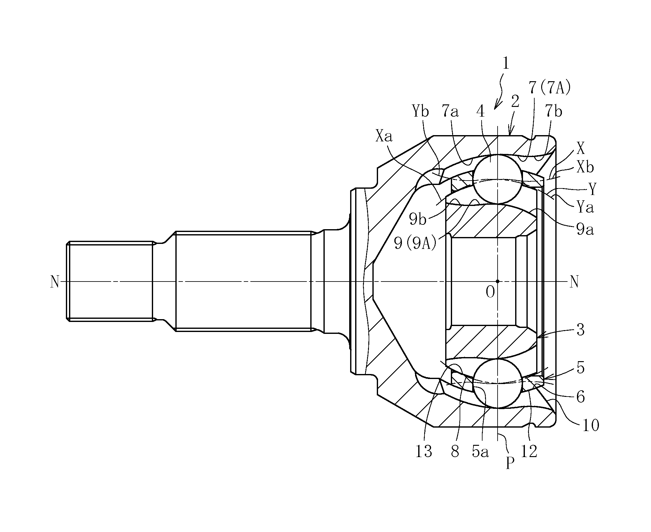
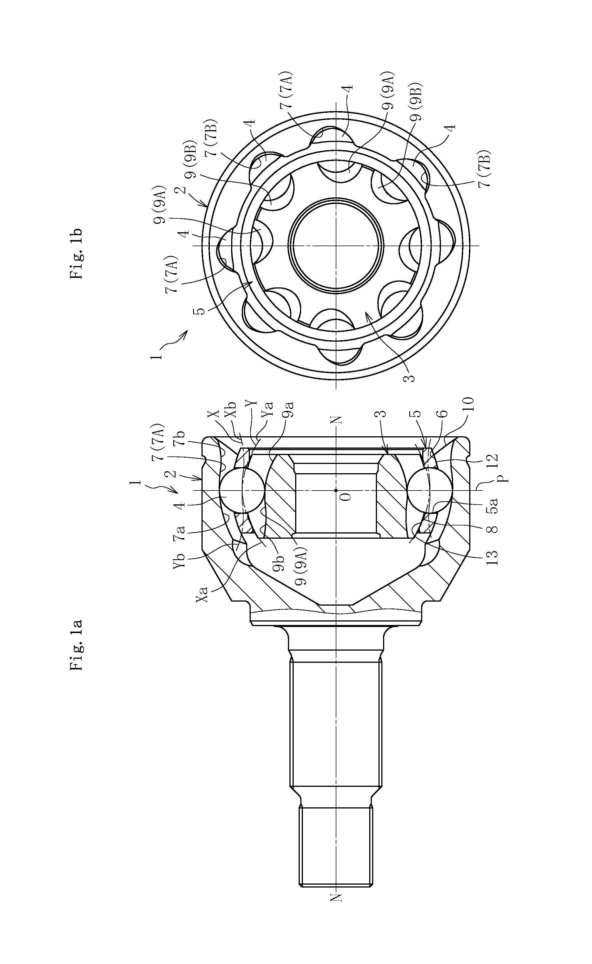
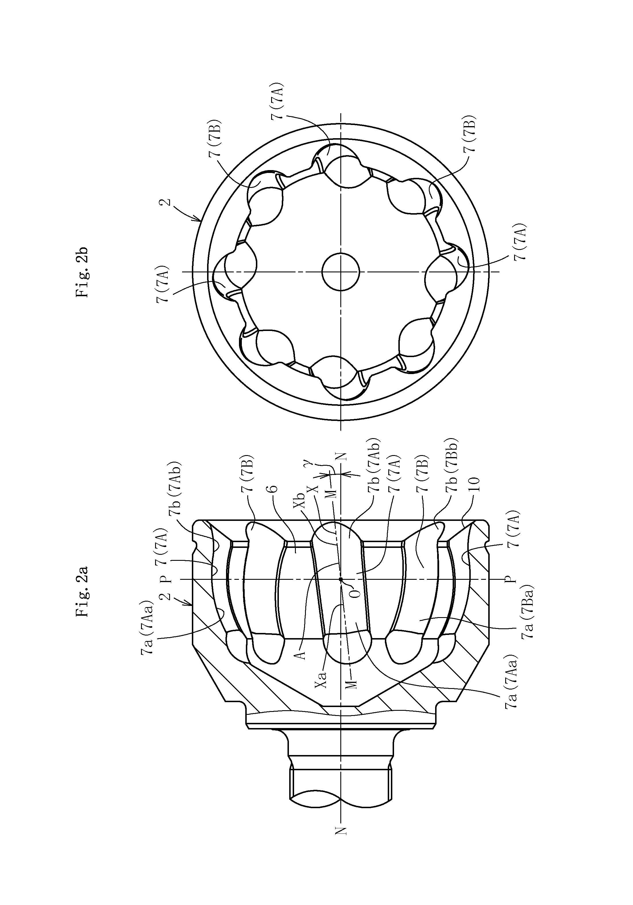
[0053]FIG. 1a is a partial vertical sectional view of a fixed type constant velocity universal joint 1 (hereinafter also referred to simply as “constant velocity universal joint 1”) according to a first embodiment of the present invention, and FIG. 1b is a front view of the constant velocity universal joint 1 as seen from an opening side thereof. The constant velocity universal joint 1 is classified into a track groove crossing type. The constant velocity universal joint 1 mainly comprises an outer joint member 2, an inner joint member 3, balls 4, and a cage 5. As illustrated also in FIG. 2, eight track grooves 7 are formed in a spherical inner peripheral surface 6 of the outer joint member 2 so as to extend along an axial direction. The track grooves 7 comprise track grooves 7 (7A and 7B) that are inclined at an angle γ in a peripheral direction with respect to a joint axial line N-N and adjacen...


PUM


Abstract

Track grooves of an outer joint member include first and second track groove portions positioned on interior and opening sides, respectively. Each first track groove portion has an arc shape with a curvature center at a position offset to the opening side with respect to a joint center. The first track groove portions are inclined in a peripheral direction of the outer joint member with respect to a joint axial line and adjacent to each other in the peripheral direction with their inclination directions opposite to each other. Each second track groove portion has a shape that is different than each of the first track groove portions so as to increase an effective track length at a maximum operating angle. The second track groove portions are connected to the first track groove portions at a position on the opening side with respect to the joint center.

Description

TECHNICAL FIELD[0001]The present invention relates to a fixed type constant velocity universal joint, and more specifically, to a fixed type constant velocity universal joint to be used in a power transmission system of automobiles and various industrial machines, for allowing only angular displacement between two shafts on a driving side and a driven side.BACKGROUND ART[0002]For example, a plunging type constant velocity universal joint capable of allowing angular displacement and axial displacement is generally assembled on an inboard side (differential side) of an automotive front drive shaft. Further, a fixed type constant velocity universal joint capable of allowing only angular displacement is generally assembled on an outboard side (wheel side) of the automotive front drive shaft.[0003]An example of the fixed type constant velocity universal joint to be used on the outboard side is described with reference to FIG. 15a, which is a vertical sectional view of a state in which a ...

Claims


Application Information

Patent Timeline
Patent Type & Authority Patents(United States)
IPC IPC(8): F16D3/2233F16D3/2245F16D3/24F16D3/223
CPCF16D3/24F16D3/2233F16D3/2245F16D2003/22306F16D2003/22309
Inventor YAMAZAKI, KENTAHIRUKAWA, HIROYASU
Owner NTN CORP
Why Eureka
Try Eureka