Endless belt, belt driving device and image forming apparatus

a technology of end-to-end belts and driving devices, which is applied in the direction of electrographic process equipment, thin material processing, instruments, etc., can solve the problems of buckling deformation, generating endless belt breakage, and liable peeling of reinforcing tapes from the belt body

Active Publication Date: 2015-12-08
CANON KK
View PDF14 Cites 21 Cited by
  • Summary
  • Abstract
  • Description
  • Claims
  • Application Information

AI Technical Summary

Problems solved by technology

Further, also in the case where a seal member or the like provided at an end portion of a belt cleaning device is contacted to the belt from the outer peripheral portion side of the belt, a force of constraint acts on the outer peripheral portion, so that the reinforcing tape is liable to be peeled off from the belt body.
When the endless belt is further driven and moved in a peeled state of the reinforcing tape, a compressive force acts on the inner peripheral portion of the belt when the belt passes through the portion where the radius of curvature is small, so that the belt body can cause buckling deformation.
During repetition of the buckling deformation in such a manner, there is a fear that a problem such that the endless belt is broken is generated.
However, according to the belt driving device described in JP-A 2002-68513, an effect of preventing breaking of the endless belt was small.
As a result, there is a fear that an inconvenience such that the reinforcing tape is peeled from the belt body is caused.
When the reinforcing tape is peeled from the belt body, there is a fear that the belt body positioned at the inner peripheral portion is broken by repetitively causing the buckling deformation.
Further, in the case where the seal member or the like provided at the end portion of the belt cleaning device is contacted to the endless belt from the outer peripheral portion side of the endless belt, there is a possibility that a problem such that also the seam reinforcing film 57 is peeled.

Method used


Image

  • Endless belt, belt driving device and image forming apparatus
  • Endless belt, belt driving device and image forming apparatus
  • Endless belt, belt driving device and image forming apparatus

Examples


embodiment 1

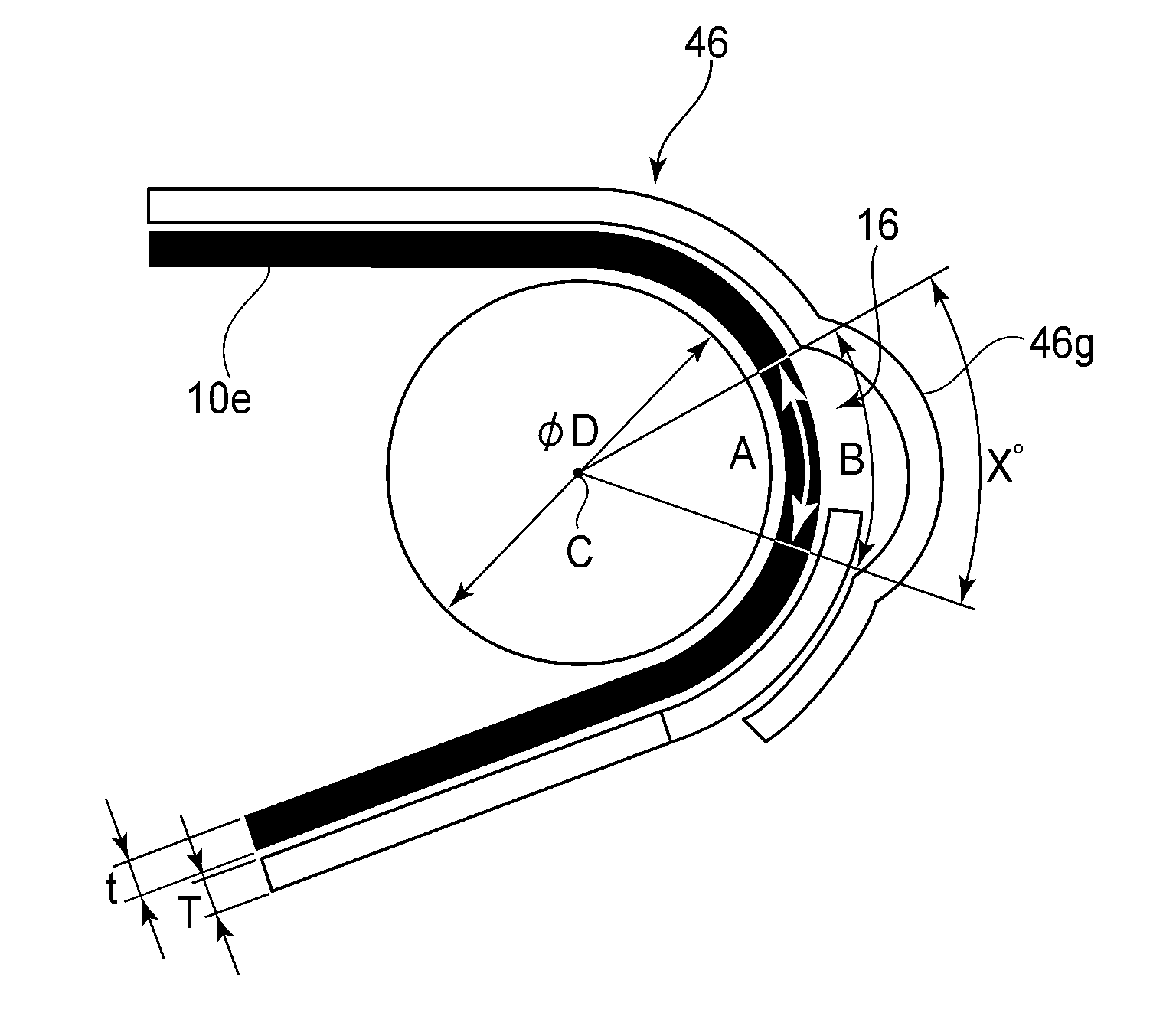
[0080]In this embodiment, as shown in FIG. 7, a reinforcing tape 46 (46a, 46b) constituted as a single long tape elongated continuously as a whole is continuously applied superposedly onto the belt body 10e at each of end portions with respect to a direction perpendicular to a circumferential direction J of the belt body 10e. In this step, as a first overlapping portion, a slack portion 16 is formed by applying the reinforcing tape 46 over the belt body 10e in a floating state of the reinforcing tape 46.

[0081]Thereafter, the continuous reinforcing tape 46 is wound around the belt body 10e plural times so as to be superposed on the slack portion 16. By constituting the reinforcing tape 46 in such a manner, the rotational direction of the belt body 10e is delimited, so that it is possible to prevent the peeling of the reinforcing tape 46. However, as described above, in order to prevent abrupt bending of the intermediary transfer belt M, a predetermined region G, which is a region of ...

embodiment 2

[0097]In this embodiment, as shown in FIG. 11, in the case where the reinforcing tape 46 is wound around the belt body 10e through a plurality of full circumferences (n circumferences), a recessed portion 26 is provided without creating a seam except for final one full circumference (n-th circumference) and is positioned at the same portion where the seam is not created. Further, only through the final one full circumference (n-th circumference), a second tape 464 of the reinforcing tape46 is applied so as to create the seam while extending over the recessed portion 26, so that the peeling of the reinforcing tape 46 is prevented.

[0098]That is, at the reinforcing portion 36 (FIG. 2) in this embodiment, as shown in FIG. 11, the reinforcing tape 46 is divided every one full circumference of the outer peripheral surface at each of the end portions with respect to the widthwise direction perpendicular to the circumferential direction J. As a result, the reinforcing tape 46 is constituted...

embodiment 3

[0135]In this embodiment, as shown in FIG. 17, the reinforcing tape 46 is constituted by one or more first tape and a second tape, and is applied onto the outer peripheral surface of the belt body 10e at each of widthwise end portions so that longitudinal end portions and the other longitudinal end portions do not overlap each other. As a result, a recessed portion 28 is formed on an outer peripheral surface 27 of the belt body 10e, and the reinforcing tape 46 is applied through a final one full circumference so as to extend over the recessed portion 28.

[0136]That is, in this embodiment, the reinforcing portion 36 (FIG. 2) is divided every winding through one full circumference on the outer peripheral surface at each of the end portions, and is constituted by the first tapes 461, 462 and 463 each shorter than the full circumference of the belt body 10e and the second tape 464 longer than the full circumference of the belt body 10e. Further, the first tapes 461, 462 and 463 are appli...


PUM


Abstract

An endless belt includes an endless belt body, and a plurality of first tapes each wound around an outer peripheral surface of the belt body. Each of the first tapes has a length shorter than a full circumference of the endless belt, and the first tapes are superposedly applied onto the belt body so that positions of first edges of the first tapes and positions of second edges of the first tapes are different from each other, respectively. A recessed portion is formed in a region between the first edges and the other edges second. In addition, a second tape having a length longer than the length of a full circumference of the endless belt is wound around the first tapes so as to extend along the recessed portion, wherein a winding end edge of the second tape overlaps a winding start edge of the second tape.

Description

FIELD OF THE INVENTION AND RELATED ART[0001]The present invention relates to an endless belt for use with an image forming apparatus such as a printer or a copying machine, and a belt driving device for moving and driving the endless belt, and relates to the image forming apparatus using the belt driving device.[0002]Among conventional image forming apparatuses, such as printers and copying machines, there is an image forming apparatus employing the endless belt, such as an intermediary transfer belt or a recording material conveyance belt.[0003]In such an image forming apparatus including the endless belt, there is a need to limit lateral shift (lateral deviation) of the belt generated during belt drive. The lateral shift of the belt (lateral belt shift) means that the endless belt moves in a widthwise direction perpendicular to a conveyance direction (rotational direction) of the endless belt.[0004]In order to enhance a lateral belt shift-limiting effect, in the case where a reinf...

Claims


Application Information

Patent Timeline
Patent Type & Authority Patents(United States)
IPC IPC(8): G03B15/16G03G15/16
CPCG03G15/1615G03G15/162B65H5/02G03G15/00G03G15/16
Inventor HATANO, FUKASHISEKI, TAKASHI
Owner CANON KK
Why Eureka
Try Eureka