Conductive plate and joint connector

a technology of conductive plates and joints, applied in the direction of connection contact materials, connection devices, transportation and packaging, etc., can solve the problems of conductive plate main body breakage and the lik

Active Publication Date: 2015-12-15
AUTONETWORKS TECH LTD +2
View PDF11 Cites 15 Cited by
  • Summary
  • Abstract
  • Description
  • Claims
  • Application Information

AI Technical Summary

Benefits of technology

[0007]The present invention is directed to a conductive plate for grounding a plurality of wires to a body of a vehicle, including a conductive plate main body including a body-side grounding portion to be grounded to the body by being bolted to the body, a plurality of terminal connecting portions provided on one end of the conductive plate main body and to be connected to wire-side terminals electrically connected to the respective wires, and a protrusion projecting from the conductive plate main body in a thickness direction of the conductive plate main body and provided to set the rigidity of the conductive plate main body to be low at a position close to the body-side grounding portion and high at a position distant from the body-side grounding portion.
[0009]According to such configurations, a stress is not concentrated at the position close to the body-side grounding portion and can be dispersed also to the position distant from the body-side grounding portion since the protrusion is provided to set the rigidity of the conductive plate main body to be lower at the position close to the body-side grounding portion than at the position distant from the body-side grounding portion. Thus, it is not necessary to thicken the conductive plate main body or use an expensive metal material, wherefore cost of the conductive plate can be suppressed low.
[0012]According to such a configuration, the rigidity of the protrusion can be appropriately adjusted by adjusting the height of the protrusion. Specifically, if the height of the protrusion is set to be high, the rigidity can be increased as compared with the case where the height of the protrusion is low.
[0014]According to such a configuration, the rigidity of the protrusion can be appropriately adjusted by adjusting the width of the protrusion. Specifically, if the width of the protrusion is set to be small, the rigidity can be increased as compared with the case where the width of the protrusion is large.
[0023]According to the present invention, it is possible to disperse a stress transmitted to a conductive plate main body.

Problems solved by technology

However, since the body-side grounding portion of the above conductive plate is firmly fixed to the body by the bolt, both vibration from the body and vibration from a wire side are transmitted to the body-side grounding portion and a stress is concentrated near the body-side grounding portion of the conductive plate main body and there is a possibility of breakage and the like of the conductive plate main body in this stress concentrated part.

Method used


Image

  • Conductive plate and joint connector
  • Conductive plate and joint connector
  • Conductive plate and joint connector

Examples


Embodiment Construction

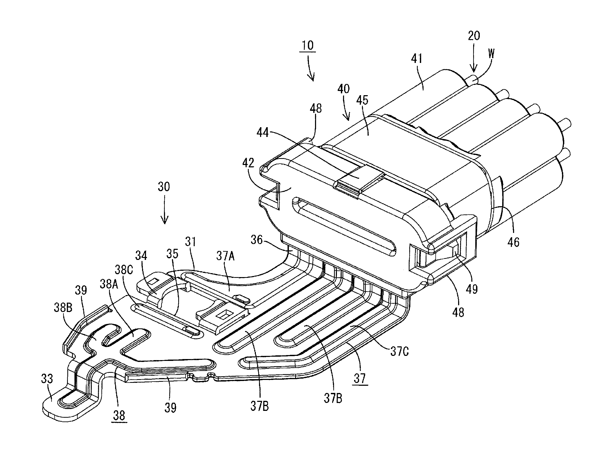
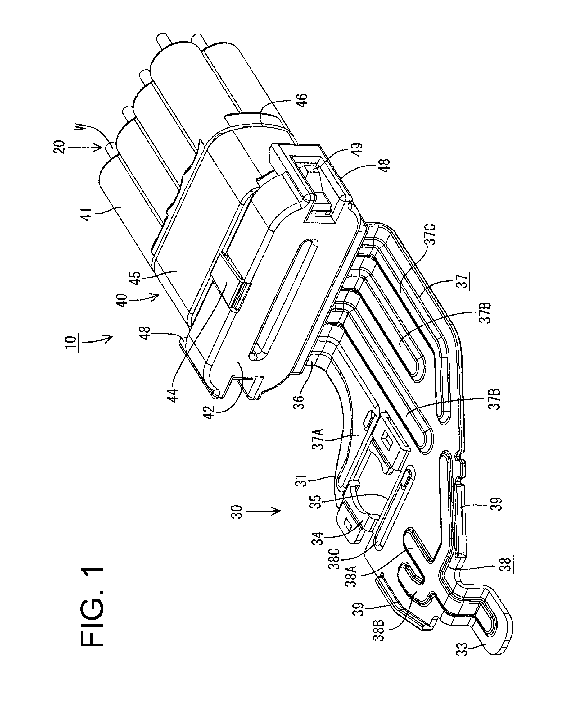
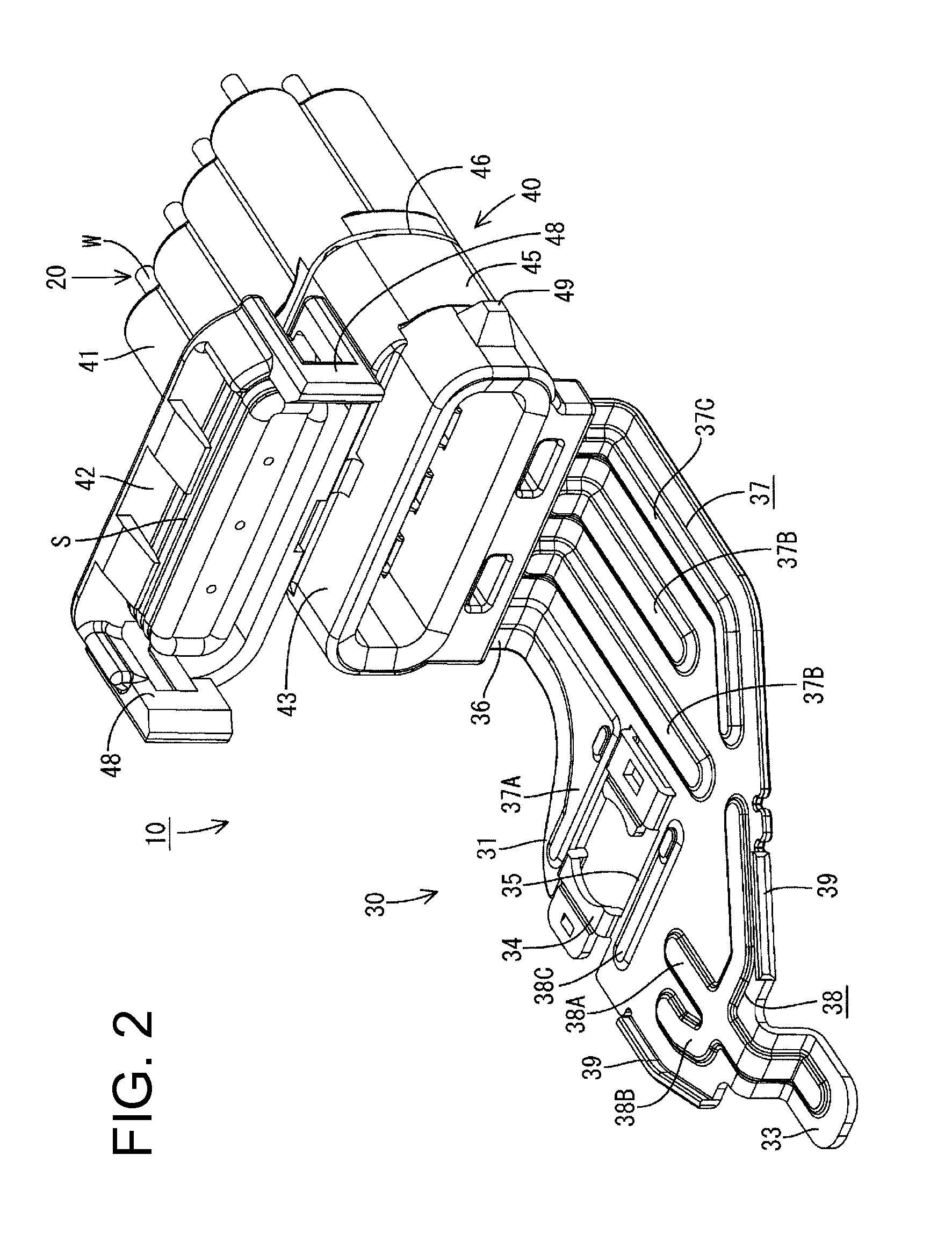
[0035]An embodiment of the present invention is described with reference to FIGS. 1 to 11. A joint connector 10 in this embodiment constitutes a part of a wiring harness in a vehicle. Specifically, the wiring harness includes a wiring harness main body formed by a plurality of wires and the joint connector 10. Out of these, the wires constituting the wiring harness main body include a plurality of first ground wires W and a second ground wire (not shown) different from the first ground wires W. These ground wires W are each composed of a conductor W1 and an insulation coating W2 covering the conductor W1, and collectively connected to a ground section of the vehicle via the joint connector 10. Although not shown, this ground section is formed by a ground bolt projecting inwardly from a wall surface of a body of the vehicle.

[0036]Each first ground wire W is for grounding a specific circuit connected to the wiring harness to the ground section and one end thereof is connected to the g...


PUM


Abstract

A conductive plate (30) for grounding a plurality of first ground wires (W) to a body of a vehicle includes a conductive plate main body (31) with a body-side grounding portion (34) to be grounded to the body by being bolted to the body. Terminal connecting portions (32B) are on one end of the conductive plate main body (31) and are to be connected to wire-side terminals (21) electrically connected to the respective first ground wires (W). A first rib group (37) and a second rib group (38) project from the conductive plate main body (31) in a thickness direction of the conductive plate main body (31) and set the rigidity of the conductive plate main body (31) to be low at a position close to the body-side grounding portion (34) and high at a position distant from the body-side grounding portion (34).

Description

BACKGROUND[0001]1. Field of the Invention[0002]The present invention relates to a conductive plate and a joint connector for grounding a plurality of wires to a body of a vehicle.[0003]2. Description of the Related Art[0004]A joint connector disclosed in Japanese Unexamined Patent Publication No. 2011-60522 is known as a joint connector of this type including a conductive plate. This joint connector includes a plurality of terminal-provided wires whose wire-side terminals are electrically connected to ends of wires, a conductive plate and a housing for holding these terminal-provided wires and conductive plate. This conductive plate includes a plurality of terminal connecting portions to be fitted to the wire-side terminals of the respective terminal-provided wires in a terminal connecting direction and a conductive plate main body including a body-side grounding portion to be grounded to a body by being bolted to a wall surface of the body, and the respective terminal connecting po...

Claims


Application Information

Patent Timeline
Patent Type & Authority Patents(United States)
IPC IPC(8): H01R33/00B60R16/02H01R4/64H01R4/34H01R13/50H01R13/52
CPCB60R16/02H01R4/64H01R4/34H01R13/501H01R13/5213H01R2201/26
Inventor OMORI, YASUOHORIUCHI, HIDEFUMIAMANO, TAKAMARUKITAGAWA, YUJITSUCHIYA, TAKASHI
Owner AUTONETWORKS TECH LTD
Why Eureka
Try Eureka