
Overload detection in a switched mode power supply

a power supply and switching mode technology, applied in the field of switching mode power supplies, can solve the problems of losing the advantages of ccp, extreme overcurrent situation, ineffective ccp, etc., and achieves the effect of easy detection and processing, increased power rating of power supplies, and no risk of breakdown

Active Publication Date: 2015-12-15
TELEFON AB LM ERICSSON (PUBL)
View PDF5 Cites 5 Cited by
  • Summary
  • Abstract
  • Description
  • Claims
  • Application Information

AI Technical Summary

Benefits of technology

The solution effectively increases the power rating of the SMPS by allowing it to operate closer to its limits without risk of breakdown, while minimizing additional components and maintaining efficiency.

Problems solved by technology

However, operation in the CCP mode gives rise to a long current tail, which means that the power supply could, under some load conditions, operate at a high enough load level and for a sufficient period of time to overheat or sustain damage.
Moreover, a more extreme over-current situation could occur during operation, such as a crowbar short-circuit, in which CCP would be ineffective.
In view of these shortcomings of CCP, power supply designers have resorted to other, more aggressive protective measures instead of CCP, such as latching the power supply's output when the input current exceeds a threshold, thereby losing the advantages of CCP.
Although these types of OCP can respond very quickly to protect the converter against rapid load changes (e.g. a crow-bar short-circuit), they cannot distinguish between such rapid load changes and more benign ones, which could be handled without shutting down the converter, for example by using CCP.
Besides the risk of false triggering, the output-latching and hiccup approaches require a guard band to be provided up to the trigger point, which leads to the further risk of the converter sustaining damage by operating within the guard band for a lengthy period of time.
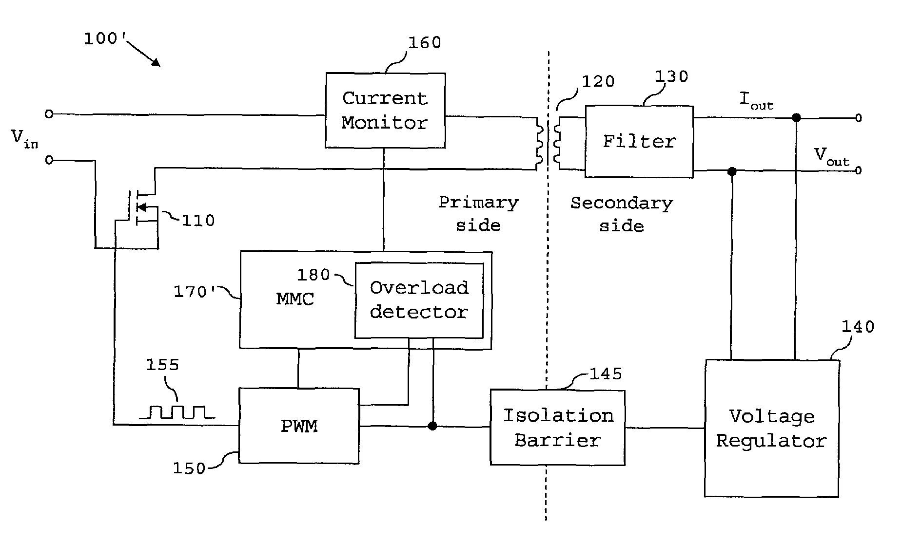
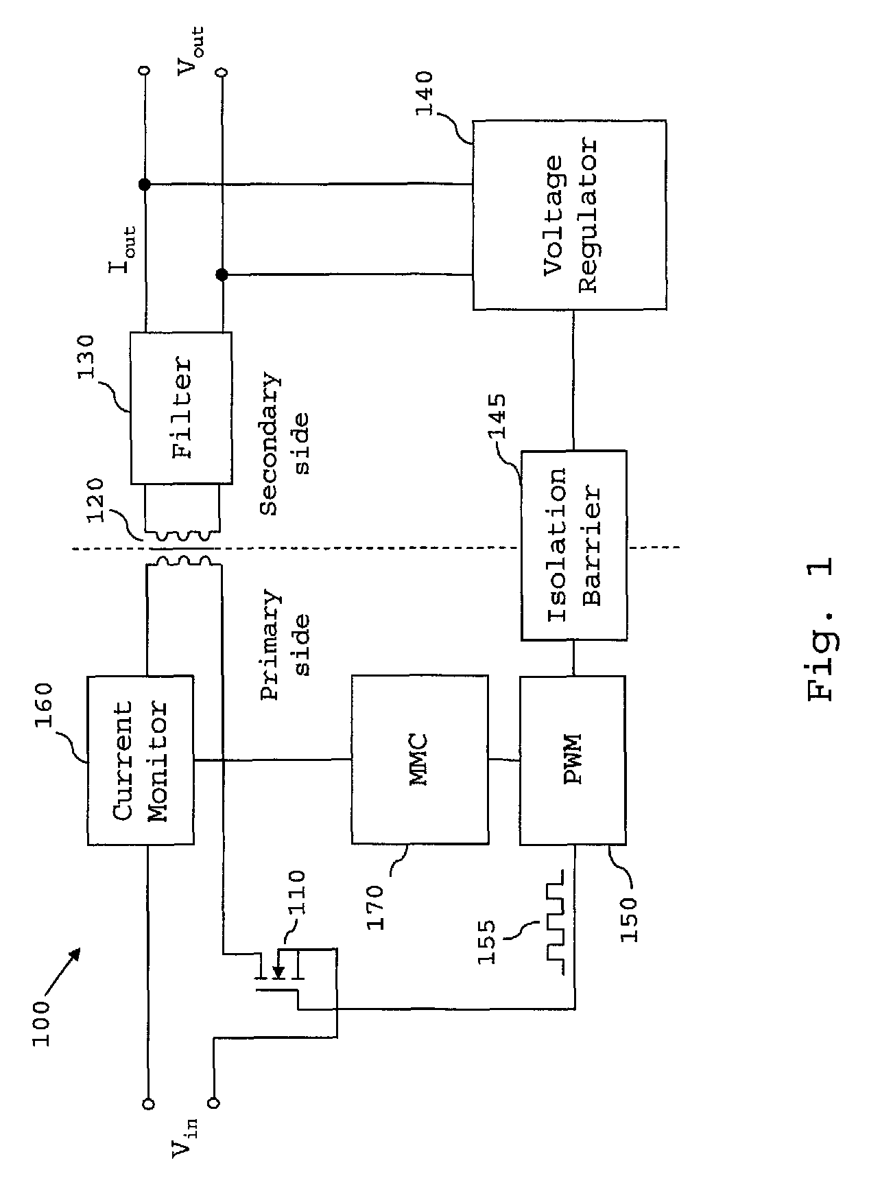
However, the input current monitored by the current monitor 160 in the converter of FIG. 1 is small and noisy, and would therefore need to be filtered and amplified before it can be analysed.
However, providing the current monitor 160 or the MMC 170 with the required additional filtering and amplification means significantly increases the component count and the fabrication cost of the converter, and since these additional components will inevitably dissipate power, also lowers the converter's efficiency.

Method used


Image

  • Overload detection in a switched mode power supply
  • Overload detection in a switched mode power supply
  • Overload detection in a switched mode power supply

Examples


example 1

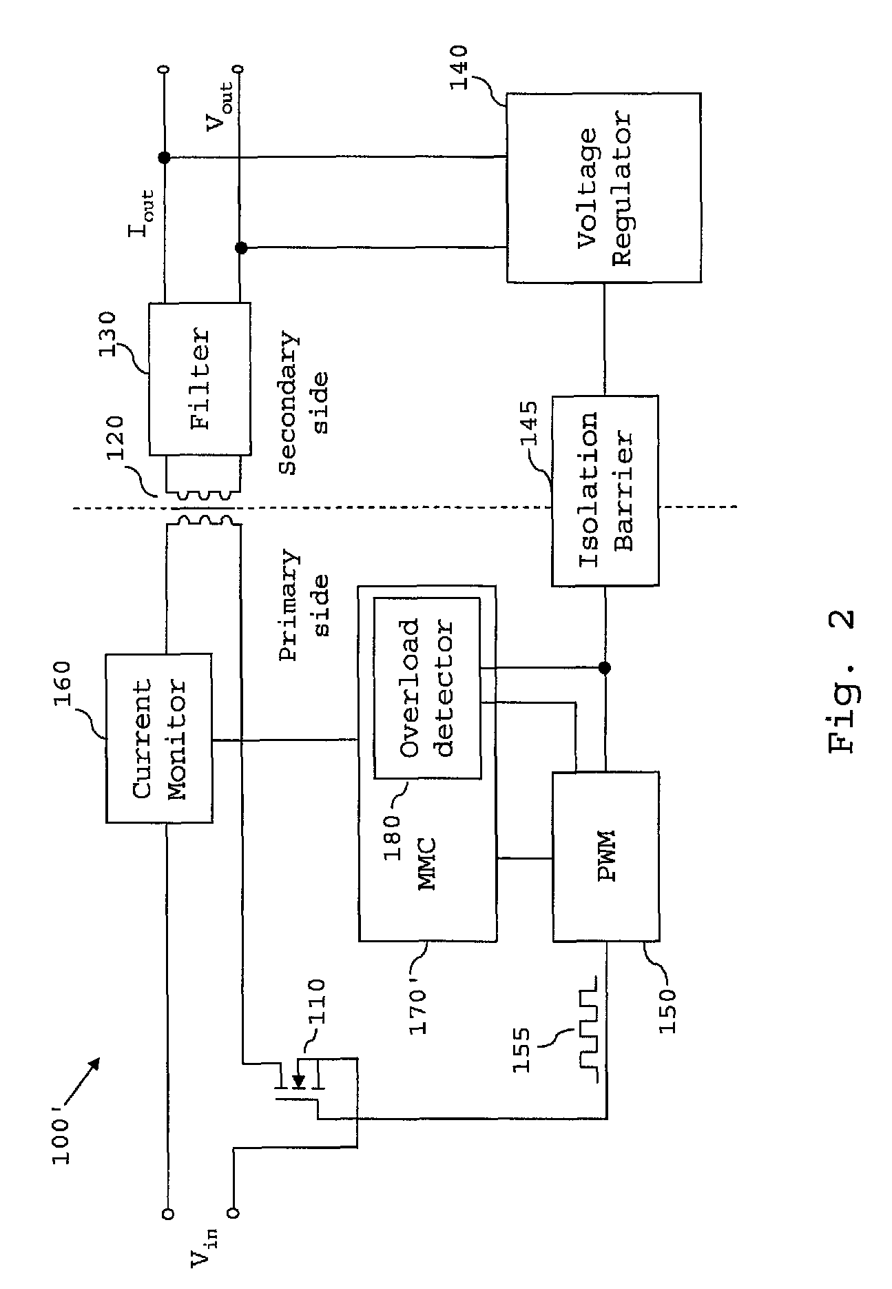
[0049]Referring first to the scheme illustrated in FIG. 6, in step S100, the overload detector 180 receives the feedback signal (error signal) via its I / O section 181 from the voltage regulator.

[0050]Then, in step S110, the overload detector 180 determines whether the feedback signal is outside a predetermined range, particularly by determining whether the COMP voltage exceeds a threshold such that it lies in the aforementioned “Fail” region shown in FIG. 5. If the feedback signal is outside the ranges encountered during normal operation (with allowance being made for transients etc. that may bring the COMP voltage within the “Dynamic” range bands), the overload detector 180 determines that the converter is in an overload state. However, if the feedback signal is not within the “Fail” region, the process loops back to step S100.

[0051]Once the overload detector has detected that the converter 100′ is an overload state in step S110, the process proceeds to step S120, in which the over...

example 2

[0052]The monitoring of the COMP signal by the overload detector 180 and its operation according to the above scheme allows the overload detector to simply and reliably detect an overload state of the DC / DC converter. Furthermore, since the COMP signal has already been subjected to filtering and amplification by the feedback circuit, the signal can be processed by the detector without the detector needing to filter or amplify the signal.

[0053]However, as noted above, short-term excursions of the feedback signal into the “Fail” region can occur if the SMPS 100′ encounters dynamic situations during its operation. For example, it may be that the power supply is charging a large capacitor, or that the speed of a fan being powered by the SMPS 100′ suddenly changes. If the power supply is to operate in an environment where such situations are expected to occur, it might be preferable to adapt the OCP mechanism of Example 1 to have a degree of tolerance to such dynamic situations. The OCP ...

example 3

[0059]A further OCP scheme will now be described with reference to FIG. 8. The operation of the overload detector 180 in accordance with this scheme reduces the risk of the detector false-triggering and unnecessarily shutting down the power supply 100′ during the power supply's start-up phase. In addition, the OCP mechanism of the present example takes into account the temperature of the power supply, which can affect the power supply's ability to safely handle over-current situations. In particular, the OCP scheme described below allows the overload detector 180 to implement protective measures more quickly at high temperatures, at which the power supply is more prone to damage when overloaded.

[0060]Similar to Example 2, the OCP scheme of the present example counts the number of COMP voltage samples that represent a COMP voltage in the “Fail” region, by increasing (or, as the case may be, decreasing) the count on a counter. When the counter is judged to have accumulated too many Fa...


PUM


Abstract

A switched mode power supply includes a switching device, the switched mode power supply being operable to convert an input voltage (Vin) to an output voltage (Vout) by switching the switching device, and a voltage regulator operable to generate a feedback signal based on at least one of the output voltage and an output current of the switched mode power supply. The power supply further comprises an overload detector, which is arranged to receive the feedback signal and operable to determine whether the feedback signal is outside a predetermined range. If the feedback signal is outside the predetermined range, the overload detector is operable to determine that the switched mode power supply is in an overload state, and when an overload state is determined, perform control to place the switched mode power supply in a non-operational state.

Description

TECHNICAL FIELD[0001]The present invention generally relates to the field of switched mode power supplies (sometimes referred to as switch mode supplies or switching mode power supplies) and more specifically to overload detection in a switched mode power supply.BACKGROUND[0002]The switched mode power supply (SMPS) is a well-known type of power converter, which has a diverse range of applications by virtue of its small size and weight, and also its typically high efficiency. For example, switched more power supplies are often used in personal computers and portable electronic devices such as cell phones. An SMPS achieves these advantages by switching a switching device such as a power MCSFET at a high frequency (usually tens to hundreds of kHz), with the frequency or duty cycle of the switching being adjusted using a feedback signal to convert an input voltage to a desired output voltage. An SMPS may take the form of a rectifier (AC / DC converter), a DC / DC converter, a frequency chan...

Claims


Application Information

Patent Timeline
Patent Type & Authority Patents(United States)
IPC IPC(8): H02M3/335H02H7/12H02M1/32
CPCH02H7/1213H02M1/32H02M3/33507
Inventor PERSSON, OSCARAPPELBERG, MIKAEL
Owner TELEFON AB LM ERICSSON (PUBL)
Learn More