
Seals and sealing methods for a surgical instrument having an articulated end effector actuated by a drive shaft

a technology of drive shaft and surgical instrument, which is applied in the direction of surgical forceps, applications, mechanical devices, etc., can solve the problems of reducing the effectiveness of surgical devices, difficult to maneuver within patients, and complicating the cleaning of instruments

Active Publication Date: 2015-12-22
INTUITIVE SURGICAL OPERATIONS INC
View PDF7 Cites 1193 Cited by
  • Summary
  • Abstract
  • Description
  • Claims
  • Application Information

AI Technical Summary

Benefits of technology

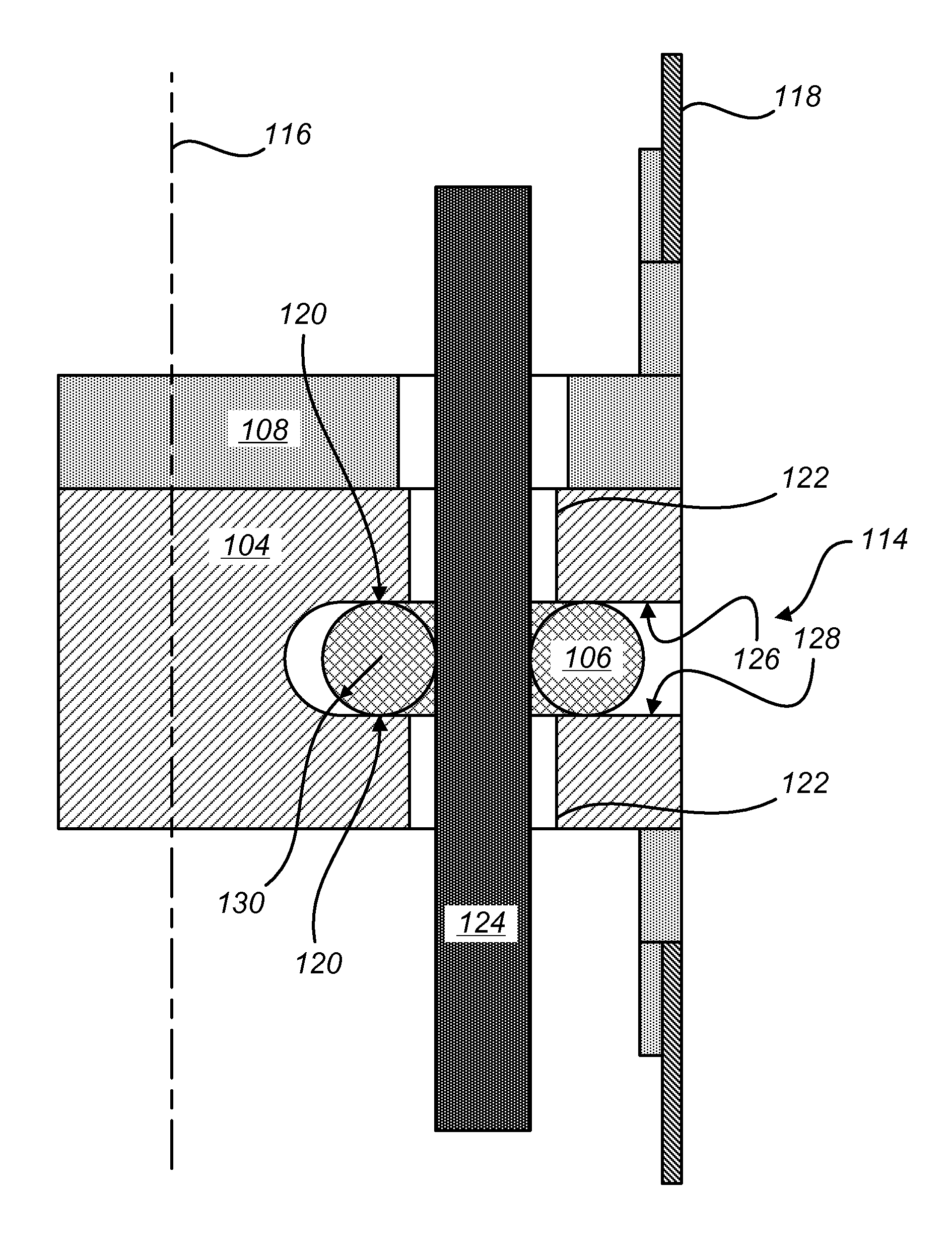
[0011]Seals and sealing methods are disclosed that can accommodate axial and lateral displacement of a drive shaft passing through a seal. The disclosed seals and sealing method can be used, for example, to prevent an insufflated gas and / or bodily fluid from traveling up an instrument shaft of a laparoscopic surgical instrument that includes one or more laterally-displacing internal drive shafts that transmit actuation torque from a proximally-disposed drive source to a distally-disposed articulated end effector. The disclosed seals can further be used to engage and seal additional mechanism components, such as control cables, that are routed within the instrument shaft to the end effector. And the disclosed seals can further be used to splice sections of the instrument shaft, thereby providing a convenient way to install such a seal.
[0023]In another aspect, a method is provided to inhibit axial flow of at least one of bodily fluids or an insufflated gas within an instrument shaft of a minimally-invasive surgical instrument having an internal drive shaft subject to lateral displacement relative to the instrument shaft. The method includes providing an internal drive shaft suitable for mounting within an instrument shaft of a minimally-invasive surgical instrument; sliding an annular sealing body radially inwardly into a slot of a valve seat within the instrument shaft so that resilient compression of the annular sealing body within the slot induces axial sealing engagement between the annular sealing body and the valve seat; and sliding the internal drive shaft axially through an aperture of the annular sealing body so that resilient expansion of the annular sealing body around the internal drive shaft induces radial sealing engagement between the internal drive shaft and the sealing body such that the sealing body is configured to inhibit axial flow of at least one of bodily fluids or an insufflated gas within the shaft while accommodating rotation of the internal drive shaft, axial displacement of the internal drive shaft, and lateral displacement of the internal drive shaft within the instrument shaft.

Problems solved by technology

Unfortunately, many known surgical devices, including known linear clamping, cutting and stapling devices, often have opposing jaws that may be difficult to maneuver within a patient.
For known devices having opposing jaws that are maneuverable within a patient, such devices may not generate sufficient clamping force for some surgical applications (e.g., tissue clamping, tissue stapling, tissue cutting, etc.), which may reduce the effectiveness of the surgical device.
Such lateral displacement, however, presents significant problems with regard to preventing the insufflated gas and / or bodily fluids from traveling up the instrument shaft, thereby complicating instrument cleaning and / or making it difficult to maintain pneumo-peritineal pressure during use in endoscopic procedures.

Method used


Image

  • Seals and sealing methods for a surgical instrument having an articulated end effector actuated by a drive shaft
  • Seals and sealing methods for a surgical instrument having an articulated end effector actuated by a drive shaft
  • Seals and sealing methods for a surgical instrument having an articulated end effector actuated by a drive shaft

Examples


Embodiment Construction

[0044]In the following description, various embodiments of the present invention will be described. For purposes of explanation, specific configurations and details are set forth in order to provide a thorough understanding of the embodiments. However, it will also be apparent to one skilled in the art that the present invention can be practiced without the specific details. Furthermore, well-known features may be omitted or simplified in order not to obscure the embodiment being described.

[0045]Minimally-Invasive Robotic Surgery

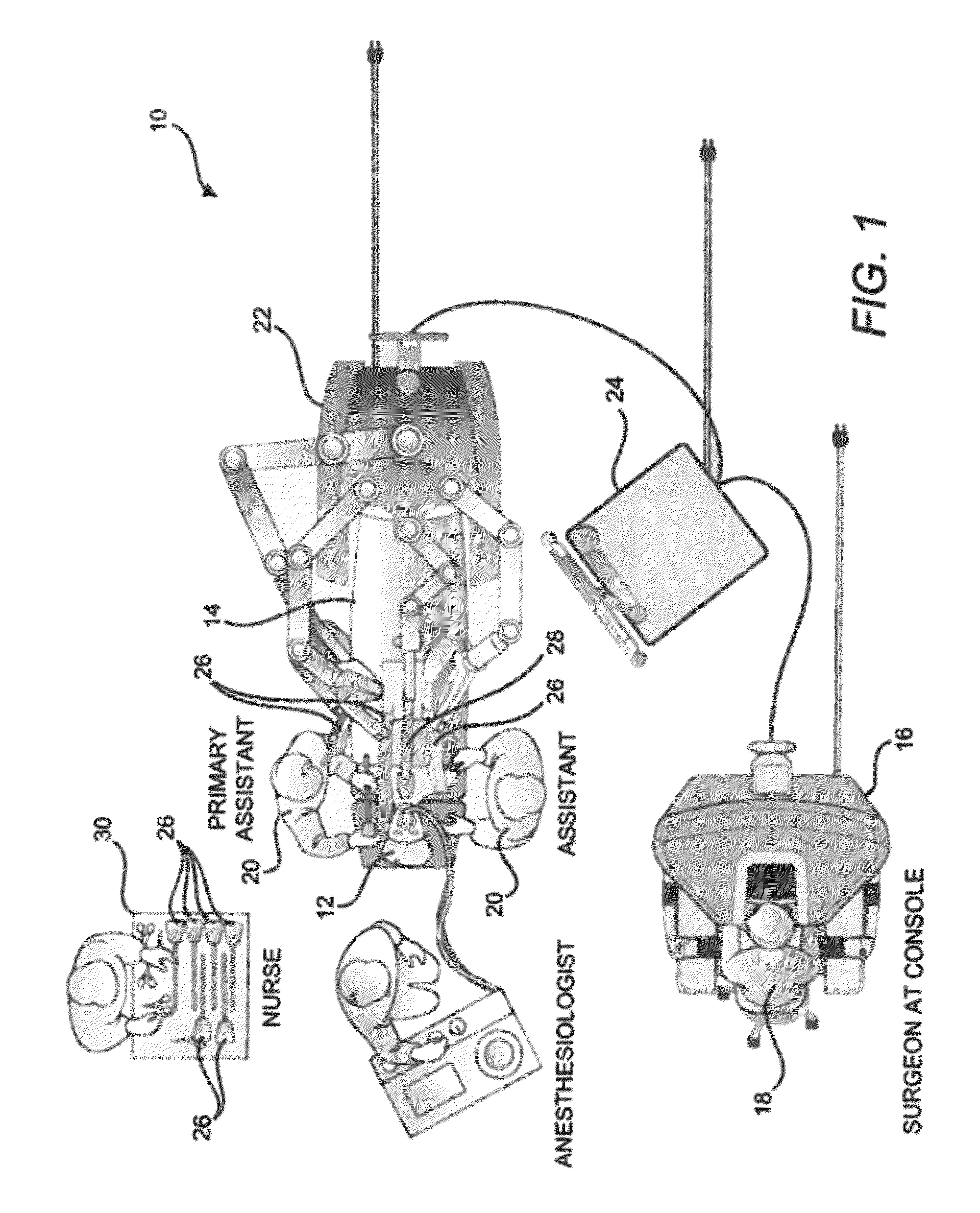
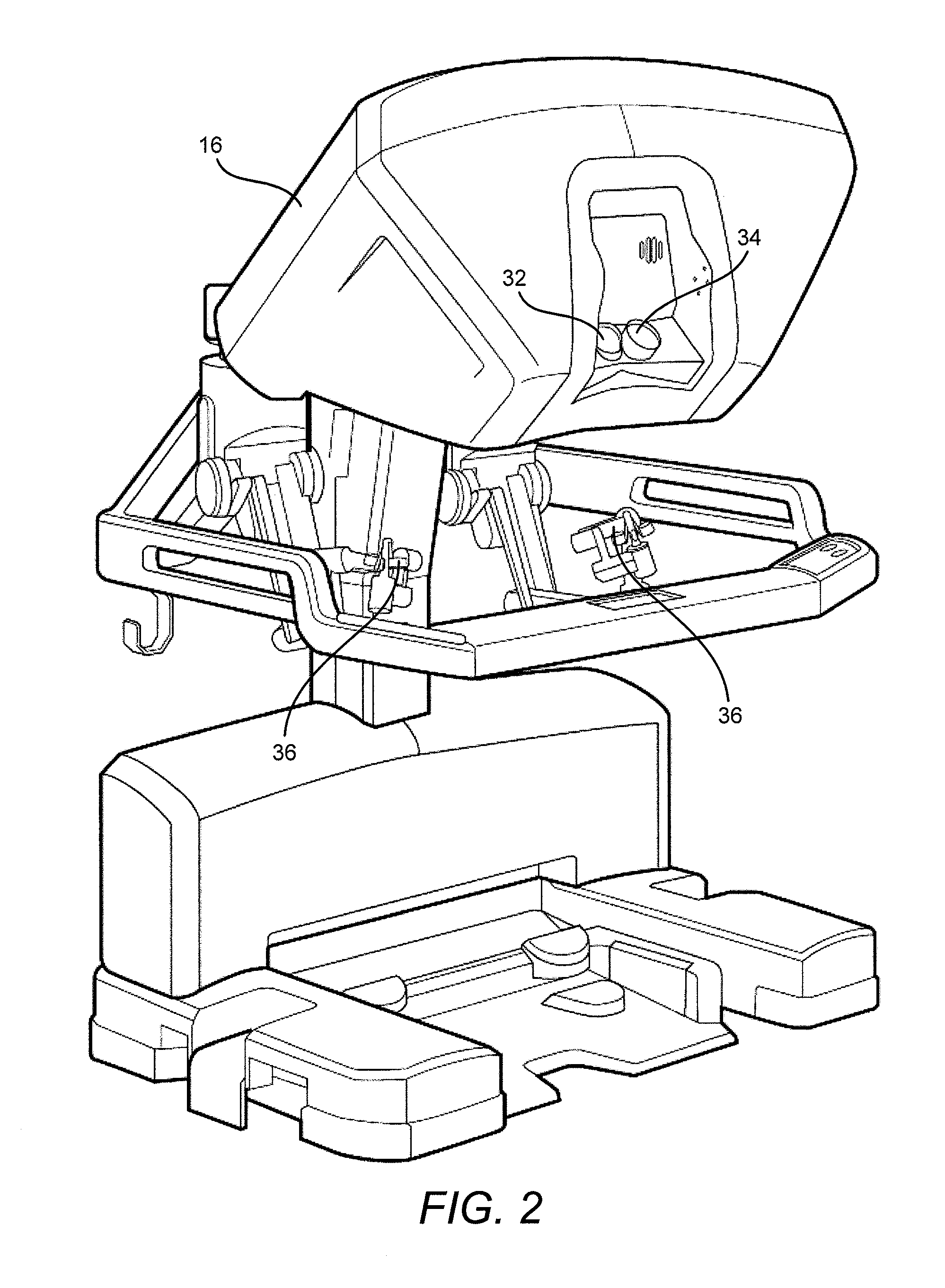
[0046]Referring now to the drawings, in which like reference numerals represent like parts throughout the several views, FIG. 1 is a plan view illustration of a Minimally-Invasive Robotic Surgical (MIRS) system 10, typically used for performing a minimally-invasive diagnostic or surgical procedure on a Patient 12 who is lying down on an Operating table 14. The system can include a Surgeon's Console 16 for use by a Surgeon 18 during the procedure. One or more...


PUM


Abstract

Sealing assemblies and methods are disclosed for sealing a surgical instrument having an internal drive shaft subject to lateral displacement. A sealing assembly includes a rigid portion shaped to interface with an instrument shaft of the surgical instrument. A laterally oriented slot is open at a radially perimeter location and configured to receive an o-ring seal via the perimeter location. Apertures are disposed on opposing sides of the slot and open to the slot. The apertures are configured to receive the drive shaft there through and are larger than the drive shaft to accommodate lateral displacement of the drive shaft. The slot includes opposing internal sides spaced to interface with opposed axial surfaces of the o-ring seal. The seal inhibits axial transmission of an insufflated gas and / or bodily fluids while accommodating lateral displacement of the drive shaft.

Description

CROSS-REFERENCES TO RELATED APPLICATIONS[0001]The present application claims the benefit of U.S. Provisional Application No. 61 / 443,200, entitled “SEALS AND SEALING METHODS FOR A SURGICAL INSTRUMENT HAVING AN ARTICULATED END EFFECTOR ACTUATED BY A DRIVE SHAFT,” filed on Feb. 15, 2011, the full disclosure of which is incorporated herein by reference.BACKGROUND[0002]Minimally-invasive surgical techniques are aimed at reducing the amount of extraneous tissue that is damaged during diagnostic or surgical procedures, thereby reducing patient recovery time, discomfort, and deleterious side effects. As a consequence, the average length of a hospital stay for standard surgery may be shortened significantly using minimally-invasive surgical techniques. Also, patient recovery times, patient discomfort, surgical side effects, and time away from work may also be reduced with minimally-invasive surgery.[0003]A common form of minimally-invasive surgery is endoscopy, and a common form of endoscopy...

Claims


Application Information

Patent Timeline
Patent Type & Authority Patents(United States)
IPC IPC(8): A61B19/00F16J15/32A61B17/29
CPCA61B19/2203F16J15/32A61B2017/2948A61B34/30A61B2034/302A61B34/37A61B34/35A61B50/00A61B17/00234A61B17/3421A61B2017/3419A61B2050/0066A61B2034/305
Inventor DUQUE, GRANTMURPHY, TODDBURBANK, WILLIAMDACHS, II, GREGORY W.
Owner INTUITIVE SURGICAL OPERATIONS INC
Learn More