Adiabatic expansion nozzle design criteria

Active Publication Date: 2015-12-22
FILIPCZAK ROBERT ANTHONY
View PDF1 Cites 0 Cited by
  • Summary
  • Abstract
  • Description
  • Claims
  • Application Information

AI Technical Summary

Benefits of technology

The new design of a dry ice production system is described in this patent. The previous design was not appropriate for hand-held fire extinguisher use due to being too small and not optimized for this purpose. The new design solves these problems and is designed to be practical and robust. The patent discusses various potential uses and firefighting applications for this new design.

Problems solved by technology

The previous design in U.S. Pat. No. 6,116,049 demonstrated the ability to produce dry ice but was not properly sized nor optimized for hand-held fire extinguisher use.

Method used


Image

  • Adiabatic expansion nozzle design criteria
  • Adiabatic expansion nozzle design criteria
  • Adiabatic expansion nozzle design criteria

Examples


Embodiment Construction

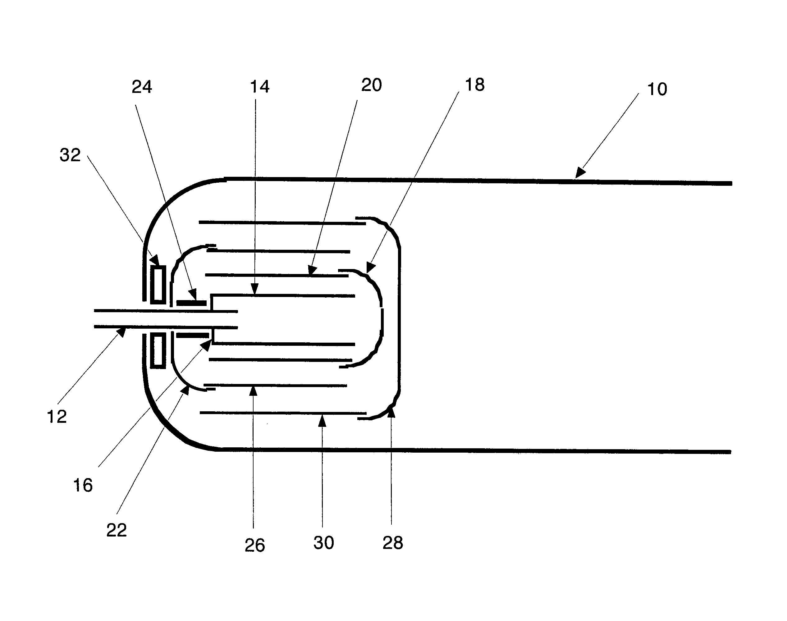
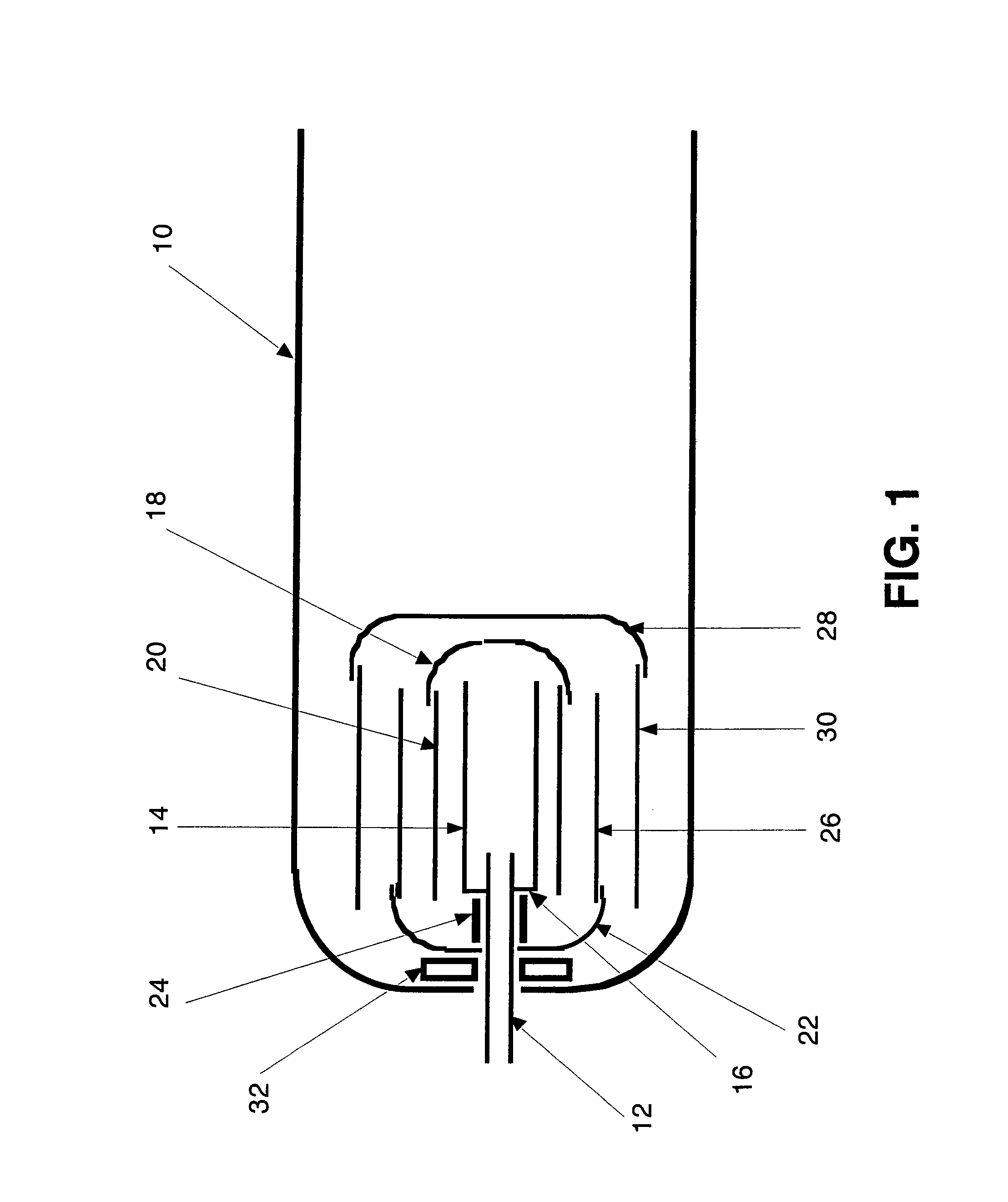
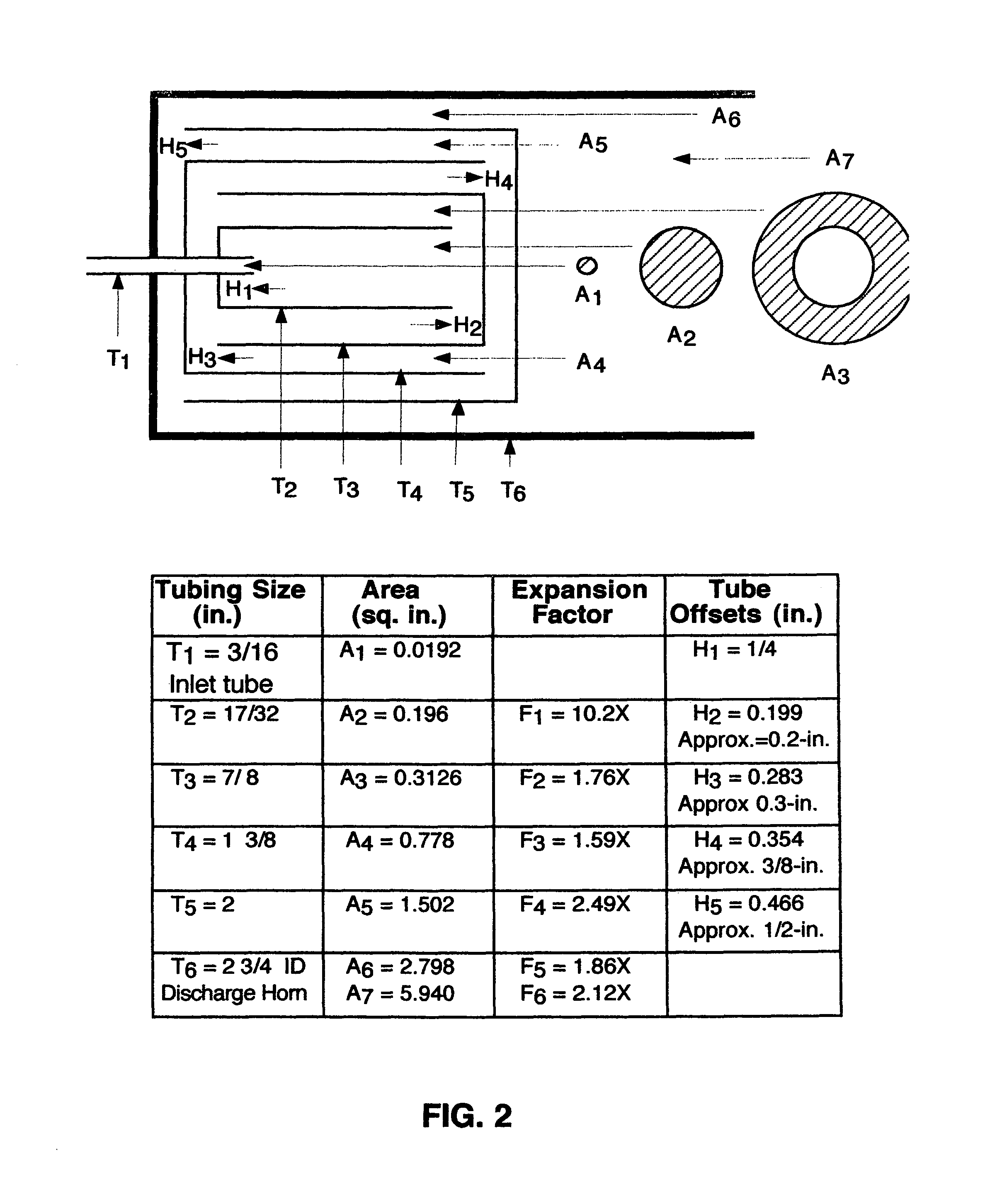
[0009]Accordingly, it is the object of this invention is to calculate and execute the designs of adiabatic expansion nozzles to fight a wide array of home, automobile, commercial and military fire scenarios. This is the specific design for the Underwriter's Laboratory 5-B rated, hand-held 5-pound carbon dioxide fire extinguisher, but other applications for the device are also explained. Calculations are presented to describe appropriate tubing diameters and tube offsets for this specific application.

[0010]It is a further object to design and produce adiabatic expansion nozzles in various sizes depending on the size of a potential fire The nozzle can be scaled to almost any size, determined only by the flow rate and size of the carbon dioxide containment vessel.

[0011]It is a further object to use an adiabatic expansion nozzle for fixed fire systems. Current carbon dioxide systems call for total flood of spaces, which is very hazardous to occupants. Deposition of dry ice stratifies th...


PUM


Abstract

Design criteria are presented for an adiabatic expansion nozzle that overcomes previous deficiencies. The original patent demonstrated that dry ice could be produced, but the device clogged, was prone to fracture, and not optimized for any specific application Calculations are presented for a single application, the hand-held, 5-pound, carbon dioxide fire extinguisher. Design considerations for other fire sizes and firefighting applications are also presented.

Description

CROSS REFERENCE TO RELATED APPLICATIONS[0001]U.S. Pat. No. 6,116,049STATEMENT OF FEDERALLY SPONSORED RESEARCH / DEVELOPMENT[0002]NonePARTIES TO A JOINT AGREEMENT[0003]NoneSEQUENCE LISTING[0004]NoneBACKGROUND[0005]The adiabatic expansion nozzle (U.S. Pat. No. 6,116,049 issued Sep. 12, 2000 to DOT, inventor Robert Filipczak) demonstrated superior firefighting ability. Later designs, submitted after the patent was issued found that a replacement nozzle could be made for the ordinary discharge horn on a hand-held, 5-pound carbon dioxide fire extinguisher. Off-the-shelf fire extinguishers made by several companies were retrofitted with a suitably sized adiabatic expansion nozzle, by unscrewing the ⅛ NPT thread on the existing discharge horn and screwing in the adiabatic expansion nozzle. The nozzle worked well but was not very robust. Solder joints failed in some versions of the nozzle and residual dry ice developed inside and could lead to clogging. While the US Government tried to licens...

Claims


Application Information

Patent Timeline
IPC IPC(8): A62C31/02
CPCA62C31/02A62C99/0027
Inventor FILIPCZAK, ROBERT ANTHONY
Owner FILIPCZAK ROBERT ANTHONY
Why Eureka
Try Eureka