Reinforcement implant for lamina with a cantilever bridge part

a technology of cantilever bridge and reinforcement implant, which is applied in the direction of spinal implants, fasteners, osteosynthesis devices, etc., can solve the problems of now unstressed bone degeneration, and achieve the effect of improving the reinforcement implant and avoiding these disadvantages

Inactive Publication Date: 2018-07-31
WALDEMAR LINK GMBH & CO
View PDF16 Cites 1 Cited by
  • Summary
  • Abstract
  • Description
  • Claims
  • Application Information

AI Technical Summary

Benefits of technology

[0009]The invention is based on the concept of using the special anchoring parts to span the resected lamina segment with a durable bridge that is robust in practice and is also easy to implant. With the two bearing surfaces oriented at an obtuse angle to each other, namely the pressure surface on the one hand and the transverse thrust surface on the other hand, a holding arrangement is created that is secure in all spatial dimensions and is free of constraint. This design avoids static overdetermination, as is typical of implants (especially designed as filler bodies) with two mutually opposite pressure surfaces that lie substantially parallel to each other. The natural elasticity in the bone is taken up in this way and is thus preserved, instead of being limited by constraint. The implant thus behaves in a way that is more physiological. This is not only favorable in terms of behavior, but also means an increased useful life of the implant by avoiding degeneration. It has indeed been found that very stiff implants, which is what constraining implants are, easily lead to degeneration of the now unstressed bone.
[0021]It will be noted that the wing extension, by virtue of its planar configuration on the outer face and by virtue of the reinforcement rib preferably provided on the inner face, can have an emergency bearing function. Should the fastening via the bridge part come loose, for example through failure of the anti-shear device, the lamina with its resection surface can then move only up to a point where it bears on the plane outer face of the wing extension and is supported there. This reliably avoids a collapse of the vertebral arch and the ensuing dramatic consequences for the patient.

Problems solved by technology

It has indeed been found that very stiff implants, which is what constraining implants are, easily lead to degeneration of the now unstressed bone.

Method used


Image

  • Reinforcement implant for lamina with a cantilever bridge part
  • Reinforcement implant for lamina with a cantilever bridge part
  • Reinforcement implant for lamina with a cantilever bridge part

Examples


Embodiment Construction

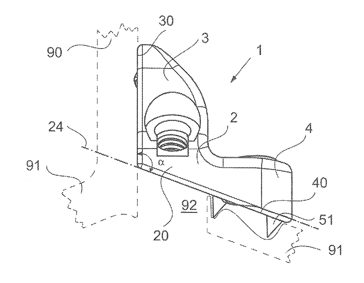
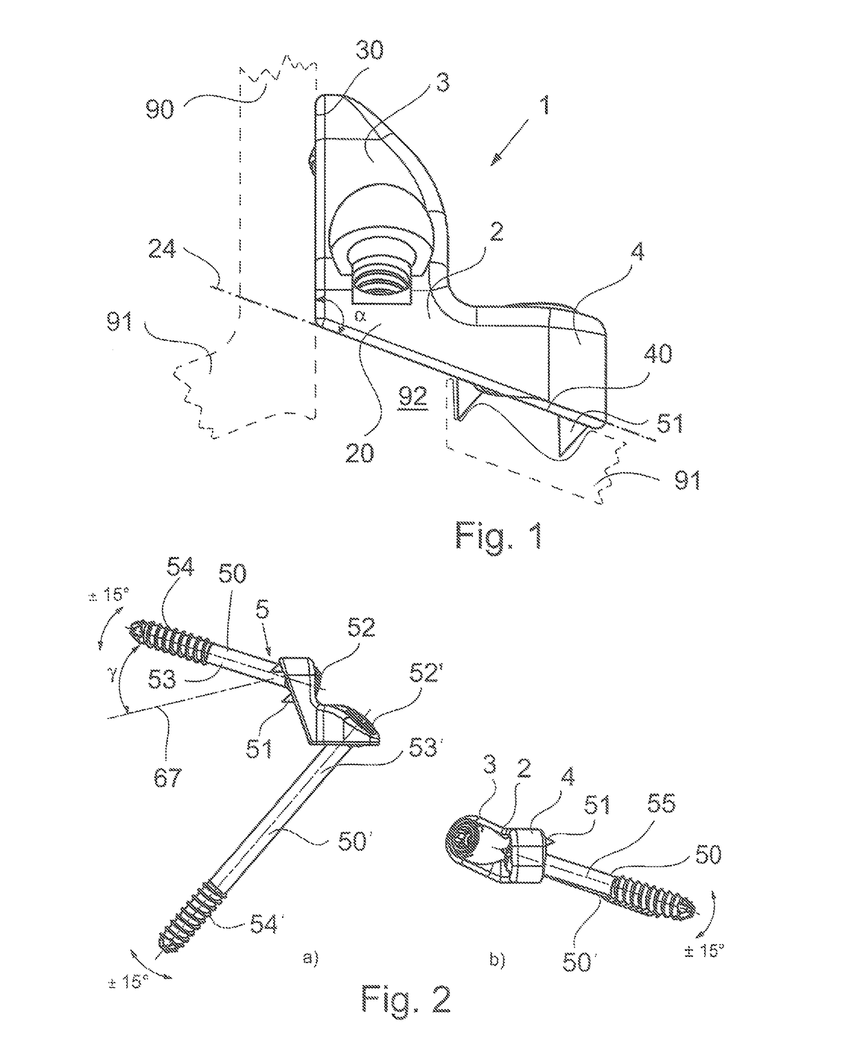
[0031]A first illustrative embodiment of a reinforcement implant according to the invention is shown in FIG. 1. It is designated in its entirety by reference number 1. It is substantially limb-shaped, with a first limb 3 and a second limb 4, which are connected to each other by a bridge part 2.

[0032]For a better understanding of the invention, there follows a detailed explanation of the structure of the vertebra and the nature of the interaction between the reinforcement implant and the vertebra. Reference is made in particular to FIGS. 6a to 6c. The vertebra 9 has a solid vertebral body 98 with two laterally protruding osseous projections 97 which, in their posterior region, are connected by an osseous arch. The osseous arch comprises a lamina 91 and, at the center thereof, a rearwardly extending projection (spinous process) 90. In the area of the transition into the lamina 91, upper and lower articular projections are arranged on each side and each form part of a facet joint 95, 9...


PUM


Abstract

A reinforcement implant comprises a cantilever part for spanning a resected area of a lamina and an anchoring part at opposite ends of the cantilever part. The first anchoring part has a pressure surface for bearing on the spinous process of the vertebra, and the second anchoring part has a transverse thrust surface for bearing on an outer face of the lamina. The pressure surface and the transverse thrust surface enclose an obtuse angle. An anti-shear device (e.g., a facet screw) is arranged on the transverse thrust surface, and one edge of the transverse thrust surface is adjoined by a load-bearing area of the cantilever part. The implant can thus be mounted in place from outside without needing to be pushed with a load-bearing action into the resected area. The resection surfaces on the lamina are free of loads, such that unevenness does not cause problems.

Description

REFERENCE TO RELATED APPLICATIONS[0001]This application claims the benefit of U.S. Provisional Patent Application No. 61 / 616,650, filed on Mar. 28, 2012, the contents of which are incorporated herein by reference.FIELD OF THE INVENTION[0002]The invention relates to a reinforcement implant for lamina with a cantilever bridge part.BACKGROUND OF THE INVENTION[0003]The spinal columns of humans or animals are constructed from a plurality of vertebrae arranged one above another. They are interconnected both in a load-bearing manner and also in an articulated manner. For this purpose, the vertebrae have a structure with a solid vertebral body with two osseous projections (pedicles) which protrude laterally and to the rear and which, in their rear region, are connected by an osseous arch. In the connection area, the osseous arch is broadened (lamina) and has, at its center, a rearwardly protruding spinous process. The spinous process and two further transverse processes on the side surfaces...

Claims


Application Information

Patent Timeline
Patent Type & Authority Patents(United States)
IPC IPC(8): A61F2/44A61B17/70A61B17/80A61B17/86
CPCA61F2/44A61B17/7064A61B17/7071A61F2/4405A61B17/8047A61B17/863A61B17/7067A61F2/442
Inventor JENSEN, HARM-IVENLINK, HELMUT D.
Owner WALDEMAR LINK GMBH & CO
Why Eureka
Try Eureka