
Vehicle

a technology of steering shaft and peripheral structure, which is applied in the field of vehicles, can solve the problems of large the large size of the resisting force change mechanism, and achieve the effects of suppressing the preventing the enlargement of the peripheral structure of the steering shaft, and smooth operation of the link mechanism

Active Publication Date: 2015-12-22
YAMAHA MOTOR CO LTD
View PDF31 Cites 21 Cited by
  • Summary
  • Abstract
  • Description
  • Claims
  • Application Information

AI Technical Summary

Benefits of technology

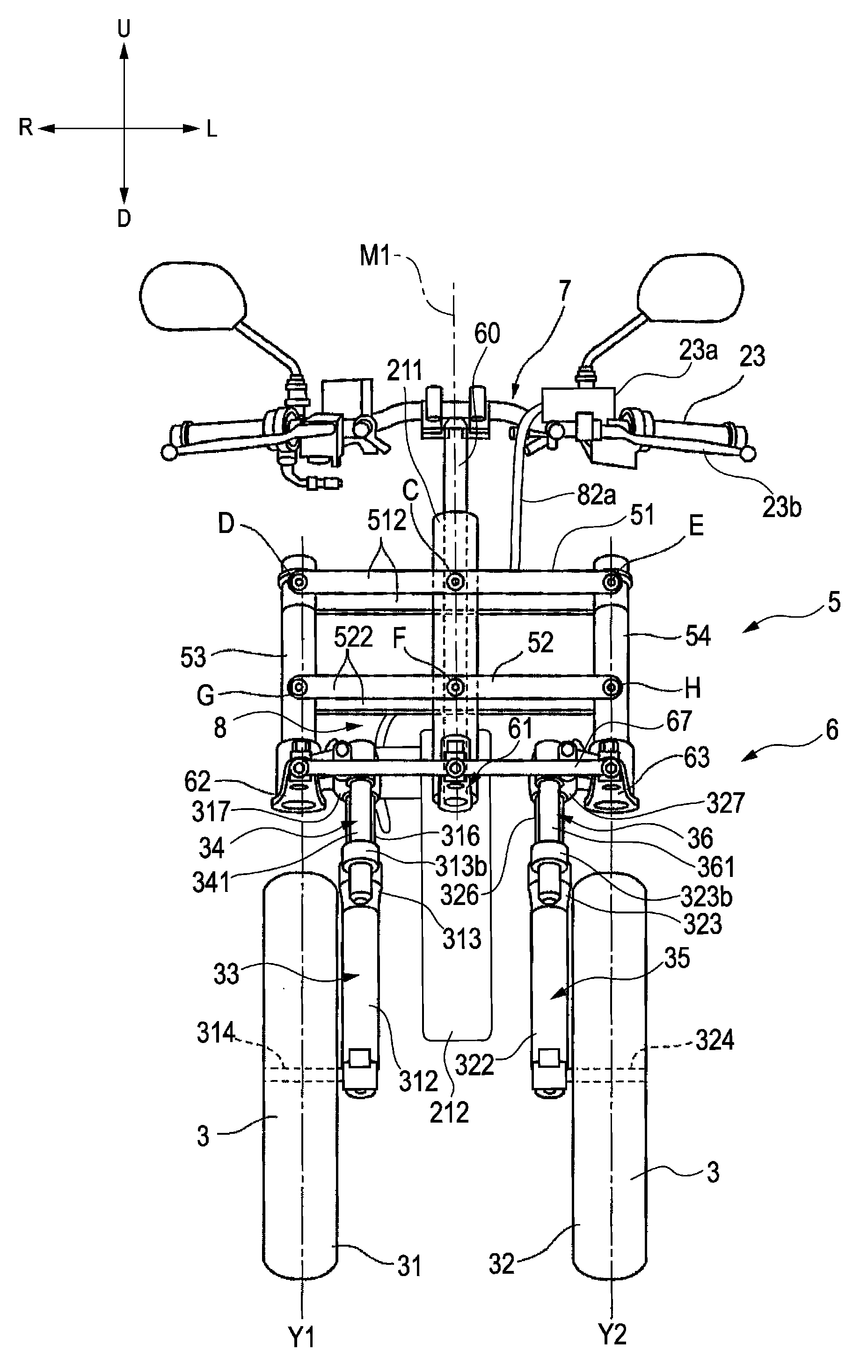
This configuration prevents the enlargement of the peripheral construction of the steering shaft while ensuring the smooth operation of the link mechanism, allowing for efficient space utilization and interference-free installation of on-board components.

Problems solved by technology

As a result, the resisting force change mechanism is large in size.
Because of this, in the vehicle equipped with the leanable body frame and the two front wheels, the peripheral construction of the steering shaft tends to be large.

Method used


Image

  • Vehicle
  • Vehicle
  • Vehicle

Examples


first preferred embodiment

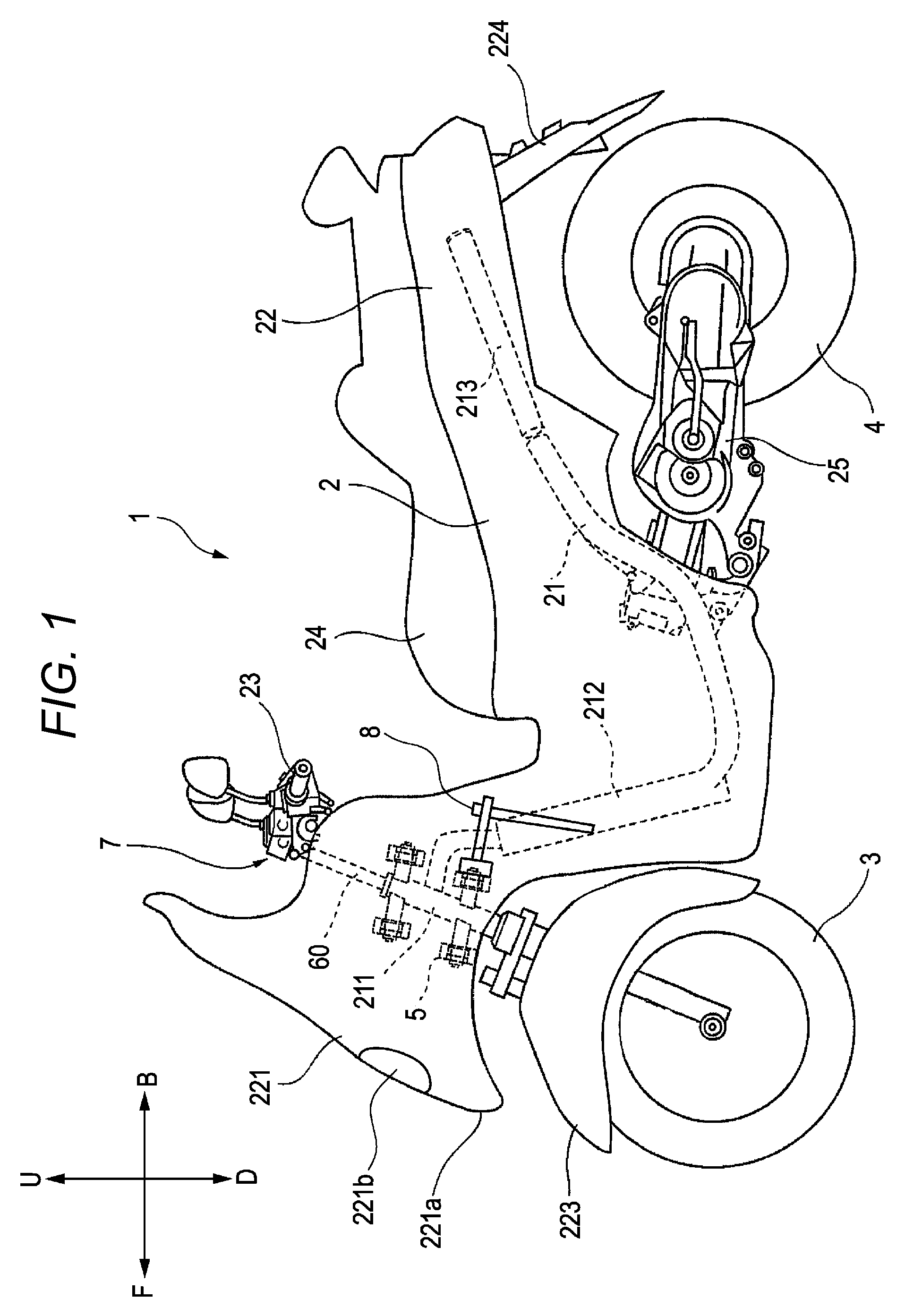
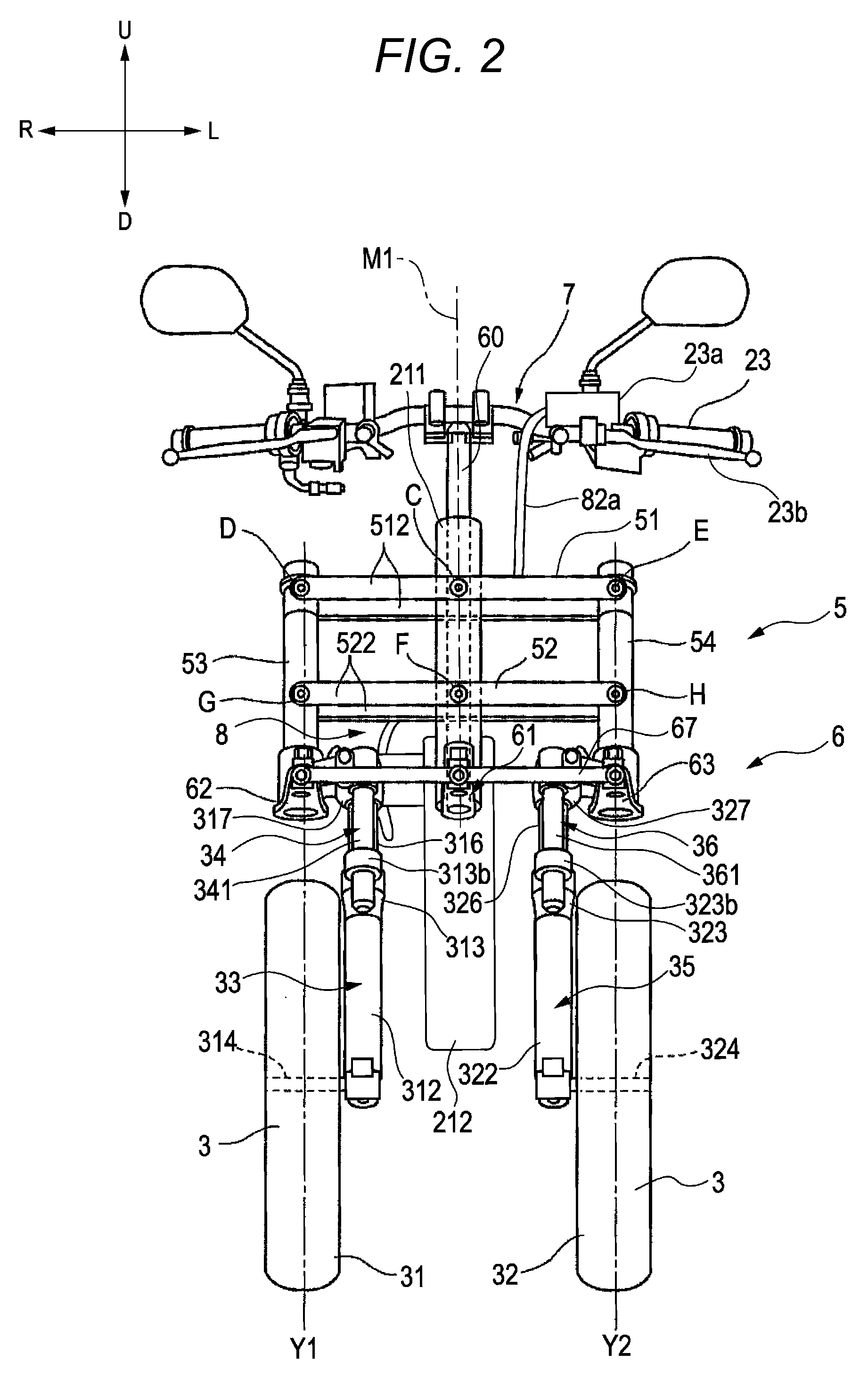
[0057]Hereinafter, a first preferred embodiment of a vehicle will be described based on FIGS. 1 to 15.

[0058]FIG. 1 shows an overall left side view of a straddle-type vehicle 1 with two front wheels which represents one type of a vehicle according to the first preferred embodiment of the present invention. Hereinafter, in the drawings, an arrow F denotes a forward direction of the vehicle 1, and an arrow B denotes a rearward direction of the vehicle 1. Additionally, in the drawings, an arrow R denotes a rightward direction of the vehicle 1, and an arrow L denotes a leftward direction of the vehicle 1. In addition, in the drawings, an arrow U denotes an upward direction of the vehicle 1, and an arrow D denotes a downward direction of the vehicle 1. When forward, rearward, leftward, and rightward directions are referred to in the following description, they denote forward, rearward, leftward, and rightward directions as seen from a rider of the vehicle 1. A transverse center indicates ...

second preferred embodiment

[0154]Referring to FIGS. 16 to 21, a three-wheeled vehicle 2001 according to a second preferred embodiment of the present invention will be described. Like reference numerals will be given to like or corresponding elements and the similar description thereof will not be repeated. Hereinafter, in the figures, an arrow F denotes a frontward direction of the three-wheeled vehicle 2001. In the figures, an arrow R denotes the right of the three-wheeled vehicle 2001. In the figures, an arrow L denotes the left of the three-wheeled vehicle 2001. An arrow U denotes a vertically upward direction. A transversely outward direction indicates a direction directed to the left or right from a transverse center.

[0155]FIG. 16 is an overall side view showing the three-wheeled vehicle 2001. In the following description, when front, rear, left, and right are referred to, they denote front, rear, left and right as seen from a rider on the three-wheeled vehicle 2001.

[0156]The three-wheeled vehicle 2001 i...


PUM


Abstract

A vehicle includes a stop element supported on a first support portion which is provided on any one of a link mechanism, a body frame, a right shock absorbing device, and a left shock absorbing device at a first end portion thereof so as to turn about a support axis of the first support portion, a lock caliper supported on a second support portion which is displaced relative to the first support portion and which is provided on any one of the link mechanism, the body frame, the right shock absorbing device, and the left shock absorbing device and which is configured to change a frictional force with the stop element, and a guide member which guides a middle portion or a second end portion of the extended member to the lock caliper. A turning angle of the stop element relative to the first support portion based on a turning operation of a first cross member and a second cross member relative to the body frame is smaller than a turning angle of the first cross member or a turning angle of the second cross member relative to the body frame based on the turning operation.

Description

BACKGROUND OF THE INVENTION[0001]1. Field of the Invention[0002]The present invention relates to a vehicle equipped with a leanable body frame and two front wheels.[0003]2. Description of the Related Art[0004]A known vehicle includes a body frame that leans in the left-right or left-and-right direction while the vehicle is cornering and two front wheels which are provided so as to be aligned side by side in the left-and-right direction of the body frame (for example, refer to Japanese Patent Unexamined Publication JP A-2005-313876, U.S. Design Pat. D547,2425, and Catalogo partidi ricambio, MP3 300 64102 ie LT Mod. ZAPM64102, Piaggio).[0005]The vehicle equipped with the leanable body frame and the two front wheels includes a link mechanism. The link mechanism includes an upper cross member and a lower cross member. In addition, the link mechanism also includes a right side rod which supports the right end portions of the upper cross member and the lower cross member and a left side r...

Claims


Application Information

Patent Timeline
Patent Type & Authority Patents(United States)
IPC IPC(8): B62K5/08B60G3/01B60G3/20B62K5/05B60G17/005B62K21/00B62K5/10B62D9/02
CPCB62K5/08B60G3/01B60G3/20B60G17/005B62K5/05B62K5/10B62K21/00B62D9/02B60G2300/45
Inventor TAKANO, KAZUHISAIIZUKA, TOSHIOKUBO, YUTAKAWATANABE, TAKAHIROMIYAMOTO, NOBORUSASAKI, KAORUOGAWA, HIROKATSU
Owner YAMAHA MOTOR CO LTD
Learn More