Transmission system for communication between downhole elements

a technology of transmission system and downhole element, applied in the field of transmission system for communication between downhole elements, can solve problems such as large gaps

Active Publication Date: 2015-12-22
ROXAR FLOW MEASUREMENT
View PDF31 Cites 3 Cited by
  • Summary
  • Abstract
  • Description
  • Claims
  • Application Information

AI Technical Summary

Benefits of technology

[0005]Thus it is an object of this invention to provide a system for communicating and supplying power to downhole electronic equipment, partially isolated in different annuli in a well, while being able to withstand harsh environment, such as large pressure differences, high temperature, and / or chemically reactive environment as well as allowing fluid flow in the annuli. This is obtained by a system as described above and characterized in the accompanying claims.
[0007]According to the preferred embodiment of the present invention, the windings are hermetically isolated from each other, and surroundings, by individual, hermetic metal shields. Furthermore, the inner core has been replaced with a metal tube for passage of fluids and an annular passage of fluids in-between the windings is maintained, and thereby created a large gap. In addition, we have inserted a metal tube of substantial thickness as a high pressure barrier in-between the windings. In order to overcome the challenge of high power loss, and poor coupling, in such a perforated and handicapped rotary transformer design, the physical sizes and geometry has been investigated, and suited materials and how to combine these has been chosen as discussed below. Thus a frequency area in which the efficiency and coupling between the two coils has been found having a power transmission efficiency of 30% to 60% under the most severe conditions.

Problems solved by technology

Furthermore, the inner core has been replaced with a metal tube for passage of fluids and an annular passage of fluids in-between the windings is maintained, and thereby created a large gap.

Method used


Image

  • Transmission system for communication between downhole elements
  • Transmission system for communication between downhole elements
  • Transmission system for communication between downhole elements

Examples


Embodiment Construction

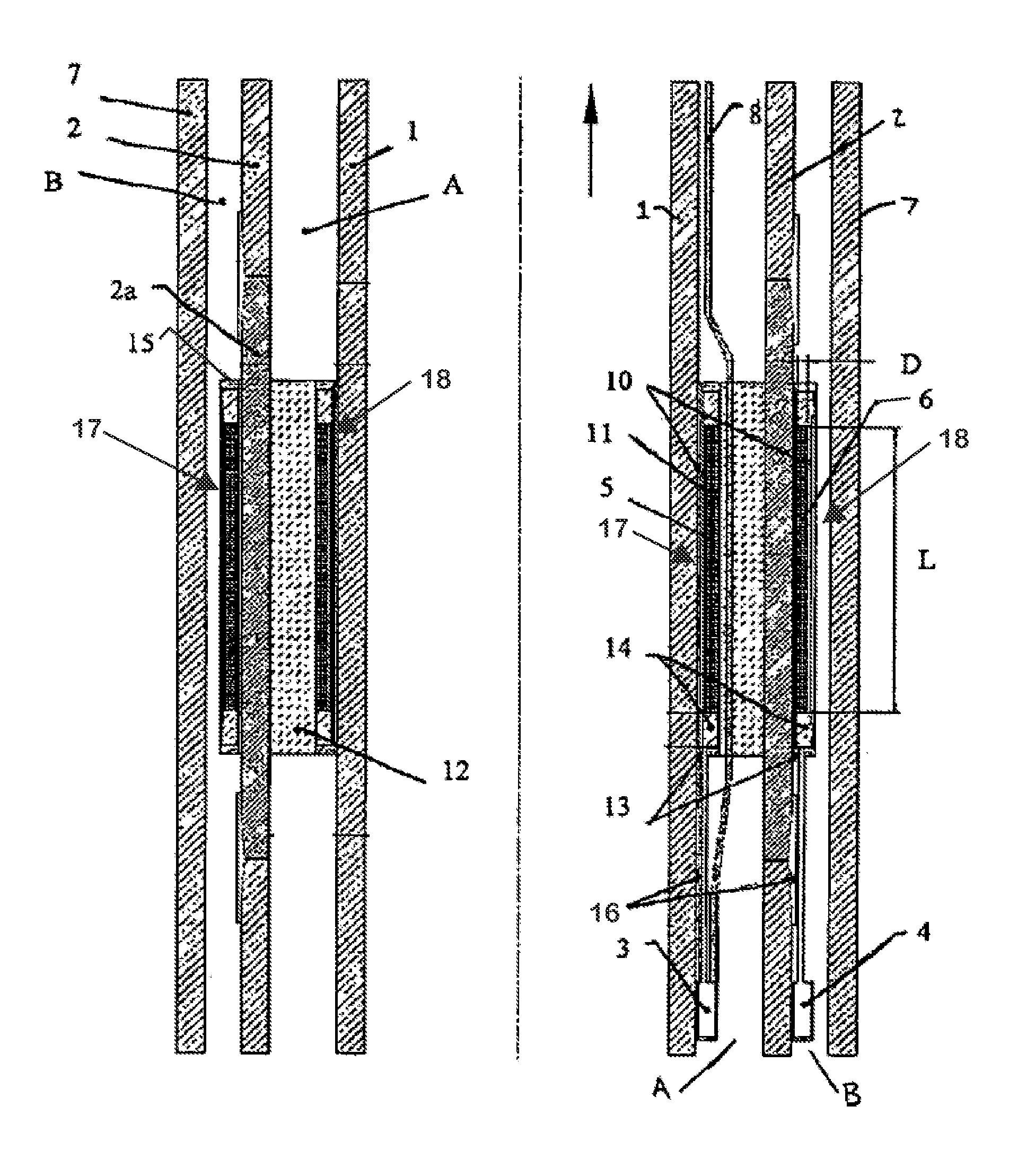
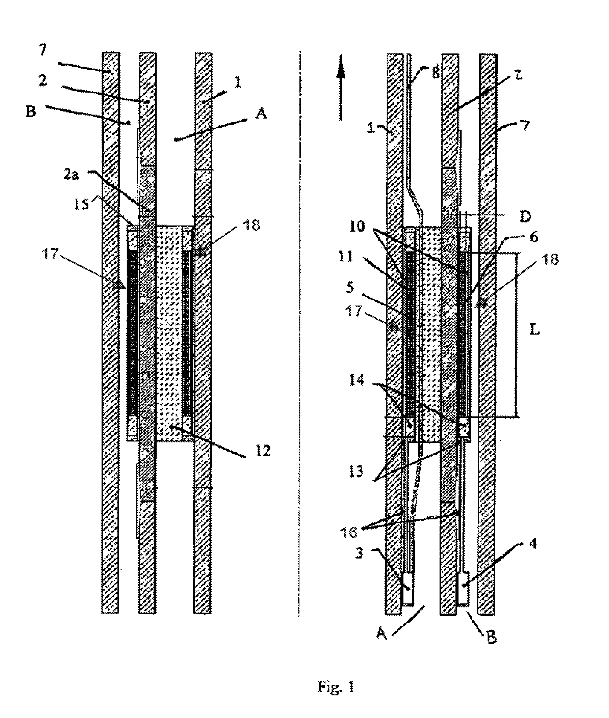
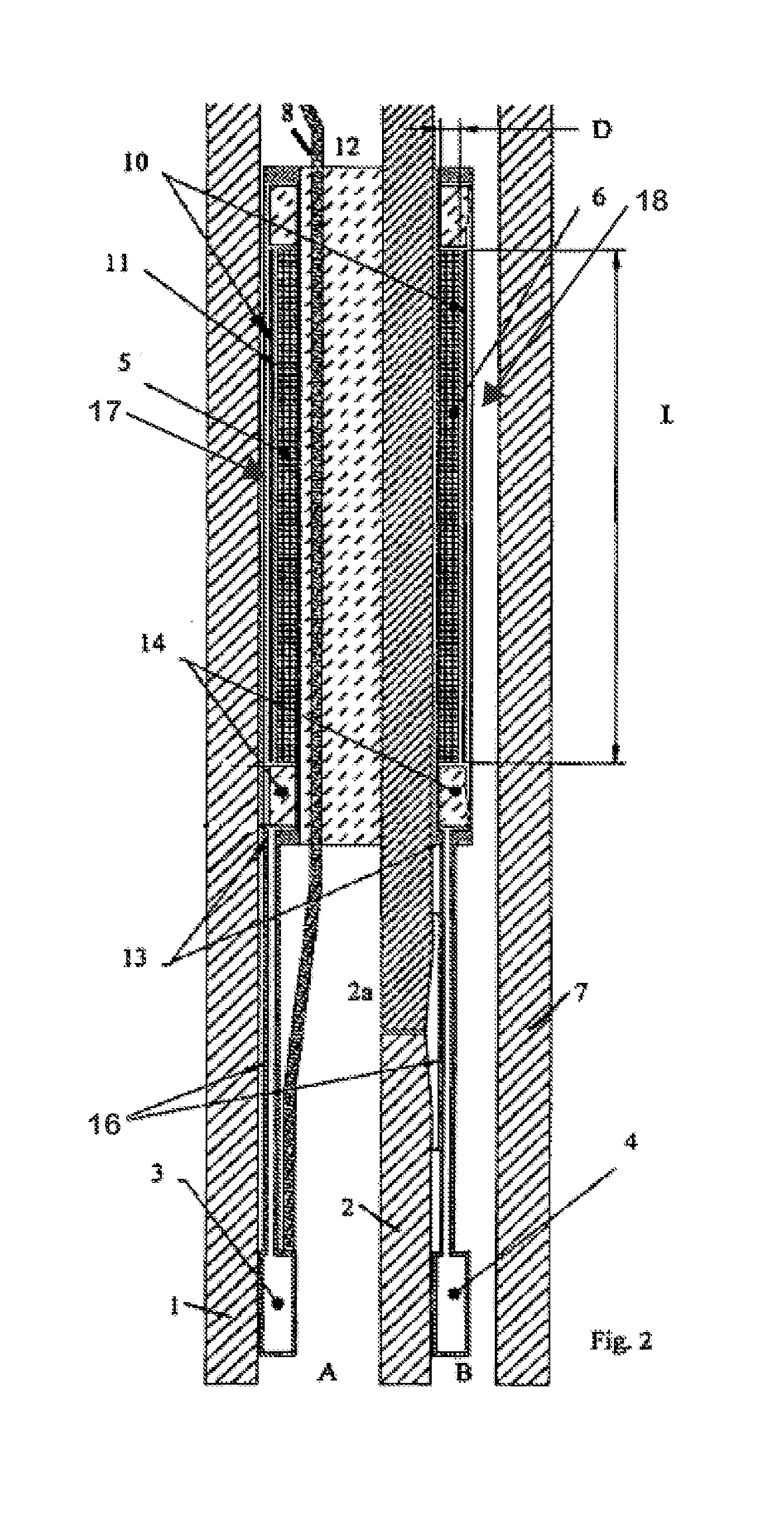
[0022]In FIG. 1 the invention is mounted onto two coaxial pipes 1,2, e.g. the inner pipe 1 being a production tubing and the outer pipe 2, A casing. The annulus between pipe 1 and 2 is A annulus. The annulus between pipe 2 and 7 is the B annulus. Pipe 7 is commonly named B casing. A sensor 3 (e.g., sensor module, gauge) is positioned onto the production tubing, pipe 1, for measuring the conditions in the annular channel, Annulus A, and as is evident from the drawings a space 12, also called “air gap” is provided between the first 1 and second 2 pipes so as to let the fluid flow in the annulus through. The control unit can provide measurements in Annulus A.

[0023]A sensor 4 (e.g., sensor module, gauge) is positioned onto the outside surface of the A casing, pipe 2, so as to provide measurements of the condition outside the second pipe 2.

[0024]The sensors 3,4 may measure a number of different parameters in the annuli, but typically the temperature and pressure is measured. For communic...


PUM


Abstract

The invention relates to a transmission system for transmitting signals between an inner and an outer unit separated by an annular pipe section wall, wherein said inner unit is provided with a first antenna and the second unit is provided with a second antenna, the antennas preferably constituted by coils, being adapted to be brought into essentially the same positions along the pipe section, wherein said pipe section is made from a material having low magnetic permeability and wherein at least one of the antennas is provided magnetic shield having high magnetic permeability, the corresponding antenna being positioned between the pipe wall and the magnetic shield and the magnetic shield extending along the length of the antenna.

Description

[0001]This invention relates to a system for transmission system for transmitting signals between an inner and an outer unit separated by an annular pipe section wall, and especially for pipes inclusing annular spaces between pipe wall.BACKGROUND OF THE INVENTION[0002]During drilling operation and hydrocarbon production / injection from / to subsurface oil and gas wells it is important to monitor the downhole conditions, e.g. to detect leaks, temperature changes and flow conditions, in the pipes casings and areas surrounding the well. This is, however, complicated by the fact that the wells usually includes a number of coaxial pipes separated by annular spaces containing pressurized fluids, produced hydrocarbons etc, and it is difficult to communicate signals e.g. both inside and outside a casing or production tubing while allowing the fluids to pass. A pressure leak from the annuli separating the tubing could saturate the ground formation, which is a potential dangerous situation. The ...

Claims


Application Information

Patent Timeline
Patent Type & Authority Patents(United States)
IPC IPC(8): E21B47/12G01V3/10H01Q7/00H04B5/00
CPCE21B47/122H01Q7/00H04B5/0081H04B5/0031E21B47/13
Inventor TARAYRE, CHRISTOPHEBLINDHEIM, ANDRE JOHANNWETTELAND, OYVIND
Owner ROXAR FLOW MEASUREMENT
Why Eureka
Try Eureka