Micro vein enhancer

a vein enhancer and micro-vein technology, applied in the field of imaging devices, can solve the problems of relativly difficult design and build a system that closely aligns the captured image and the projected image, and achieve the effect of reducing and/or reducing the amount of botched attempts to pierce the vein and being convenient to opera

Active Publication Date: 2012-08-28
ACCUVEIN
View PDF51 Cites 21 Cited by
  • Summary
  • Abstract
  • Description
  • Claims
  • Application Information

AI Technical Summary

Benefits of technology

[0011]The present invention is a Miniature Vein Enhancer that includes a Miniature Projection Head. The Miniature Projection Head of the present invention implements a polarized laser light. This diminishes the effects of specular reflection off the surface of the skin. The Veinviewer Imaging System, produced by Luminetx, uses a polarized filter to polarize the LED light. This polarized LED light is then rotated 90° in front of the camera, thus causing increased power loss.
[0022]It is still a further object of the present invention to make a Miniature Vein Enhancer that is easy to operate.

Problems solved by technology

Given that the CCD imager and the image projector are both two dimensional, and do not occupy the same point in space, it is relatively difficult to design and build a system that closely aligns the captured image and the projected image.

Method used


Image

  • Micro vein enhancer
  • Micro vein enhancer
  • Micro vein enhancer

Examples


first embodiment

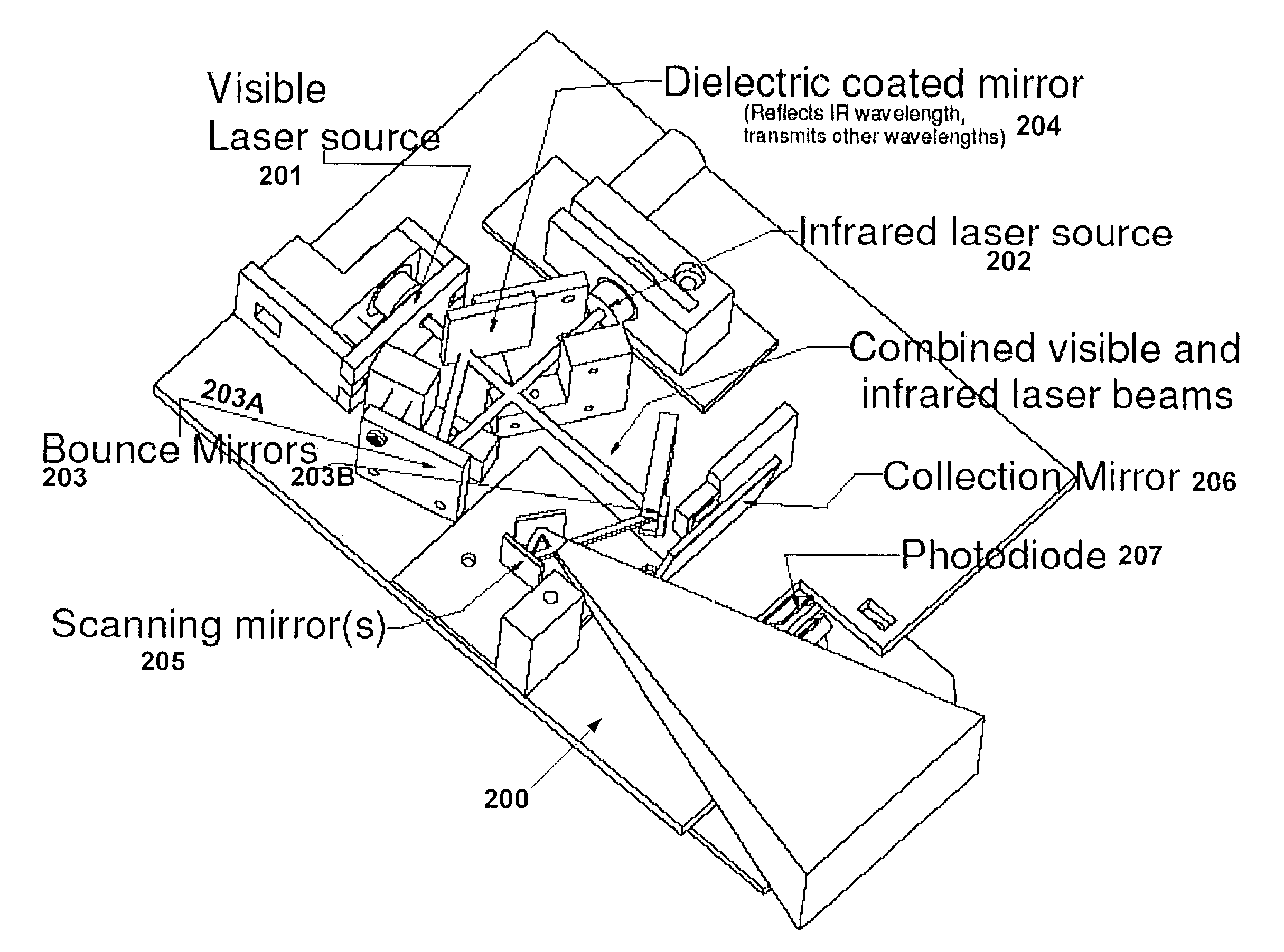
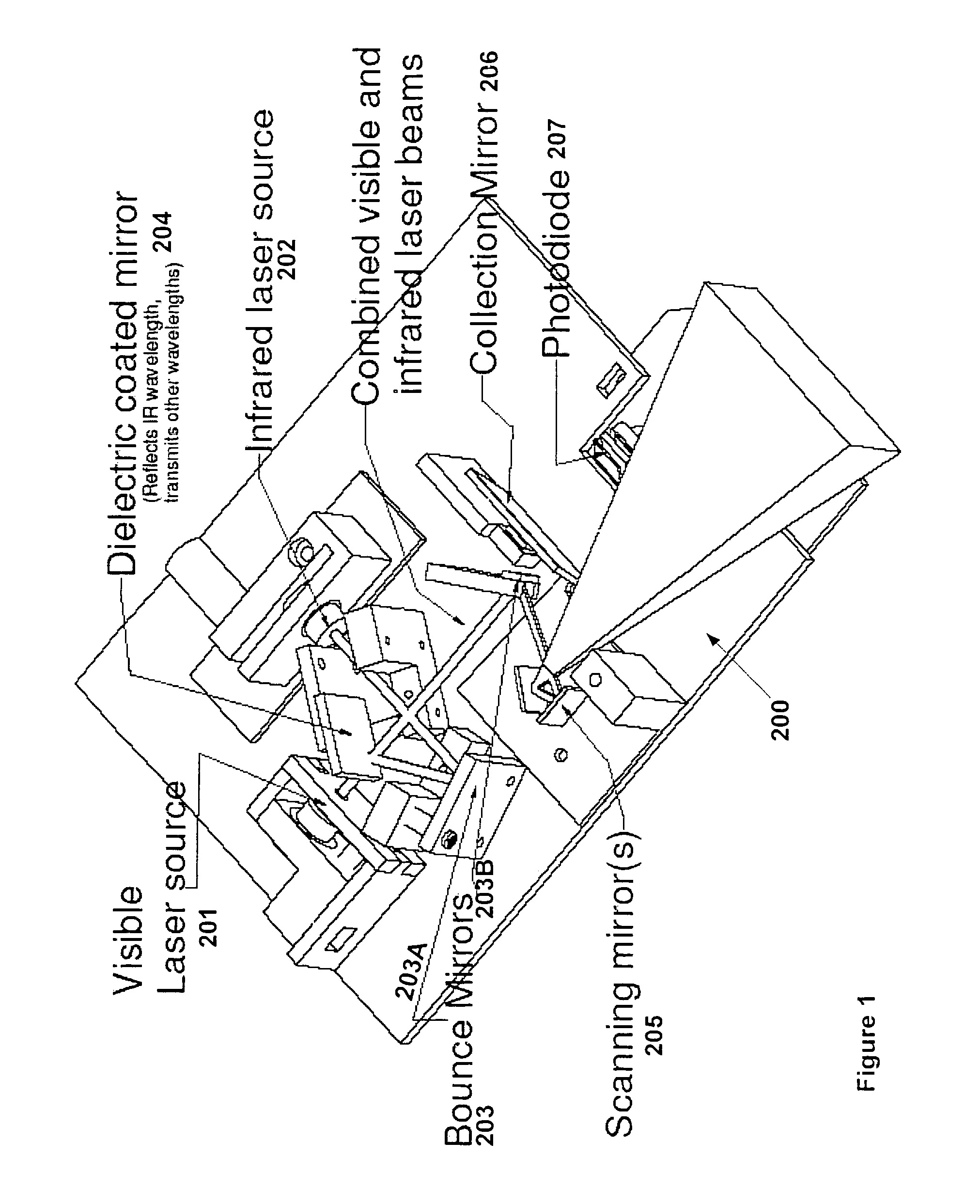
[0046]Regarding the first embodiment, it is necessary to co-axially align the two lasers. Co-axially aligning the two lasers can be achieved in a multitude of ways. Two methods that have proven to be effective include implementing, either, a dielectric mirror or a polarizer.

[0047]The first configuration includes a first laser calibrated to transmit light in the Infrared (hereinafter IF) spectrum, that is 740 nm, and a second laser calibrated to transmit a light in the red color spectrum, that is ≈638 nm. The first configuration, as mentioned above, implements a hot mirror 204 coated with a Dichroic substance, which separates and directs the light onto two separate diodes. This system allows the visible and IR laser reflections in real-time without the use of a memory chip. With this embodiment the 638 nm laser 201 is oriented behind the dielectric mirror. The dielectric mirror is selected so that the 638 nm laser light passed through but the 740 nm is reflected. The 740 nm laser is ...

second embodiment

[0049]Regarding the second embodiment, the two lasers are multiplexed. It has been noted that the signal received by the 740 nm PD of the present invention is representative of both the veins and the surface topology of the patient. Put another way, the surface of the patient affects the reflected signal. This is not desirable, in that the area of interest is the veins of the patient and not the surface topology of the patient. Thus, by using a second PD for receiving the 630 nm reflected signal, the 630 nm signal (the topology) can be subtracted from the 740 nm signal (topology+veins) yielding a signal that is solely the veins (topology+veins-topology=veins). In this system the microprocessor 250 or state machine circuit, as seen in FIG. 8, can record the reflection from the visible laser and the IR laser can be turned on for one frame, every other frame, or every other scan line. Hence, a new signal would contain a combined laser reflection. The new signal would then be subtracted...


PUM


Abstract

The present invention is a Miniature Vein Enhancer that includes a Miniature Projection Head. The Miniature Projection Head may be operated in one of three modes, AFM, DBM, and RTM. The Miniature Projection Head of the present invention projects an image of the veins of a patient, which aids the practitioner in pinpointing a vein for an intravenous drip, blood test, and the like. The Miniature projection head may have a cavity for a power source or it may have a power source located in a body portion of the Miniature Vein Enhancer. The Miniature Vein Enhancer may be attached to one of several improved needle protectors, or the Miniature Vein Enhancer may be attached to a body similar to a flashlight for hand held use. The Miniature Vein Enhancer of the present invention may also be attached to a magnifying glass, a flat panel display, and the like.

Description

[0001]This application is a continuation in part of application Ser. No. 11 / 478,322, filed on Jun. 29, 2006 and also claims priority on provisional patent application entitled Three Dimensional Imaging of Veins, Application No. 60 / 817,623, also filed on Jun. 29, 2006, all disclosures of which are hereby incorporated by reference.FIELD OF INVENTION[0002]The invention described herein relates generally to an imaging device, in particular, an imaging means for enhancing visualization of veins, arteries and other subcutaneous structures of the body for facilitating fluid insertion into or extraction from the body or otherwise visualizing subcutaneous structures for diagnosis of the medical condition of a patient or administration of medical treatment to a patient.BACKGROUND OF THE INVENTION[0003]A visit to a doctor's office, a clinic or a hospital may necessitate vascular access that is, the insertion of a needle or catheter into a patient's vein or artery. These procedures may be requi...

Claims


Application Information

Patent Timeline
Patent Type & Authority Patents(United States)
IPC IPC(8): A61B6/00
CPCA61B5/0059A61B5/0062A61M5/427A61B5/489A61B5/441A61B5/0064A61B2090/366
Inventor GOLDMAN, RONHUNT, DAVIDMOCK, MARKMARSHALL, GRAHAMCONLON, STEPHEN P.ROTH, BOB
Owner ACCUVEIN
Why Eureka
Try Eureka