
Method and apparatus for controlling a surface scanning coordinate measuring machine

a coordinate measuring machine and surface scanning technology, applied in the direction of electric programme control, program control, instruments, etc., can solve the problems of increasing costs, reducing throughput, and time-consuming techniques, so as to minimize the impact of tip touchdown on the speed of the surface scanning measure machin

Active Publication Date: 2015-12-22
HEXAGON TECH CENT GMBH
View PDF15 Cites 0 Cited by
  • Summary
  • Abstract
  • Description
  • Claims
  • Application Information

AI Technical Summary

Benefits of technology

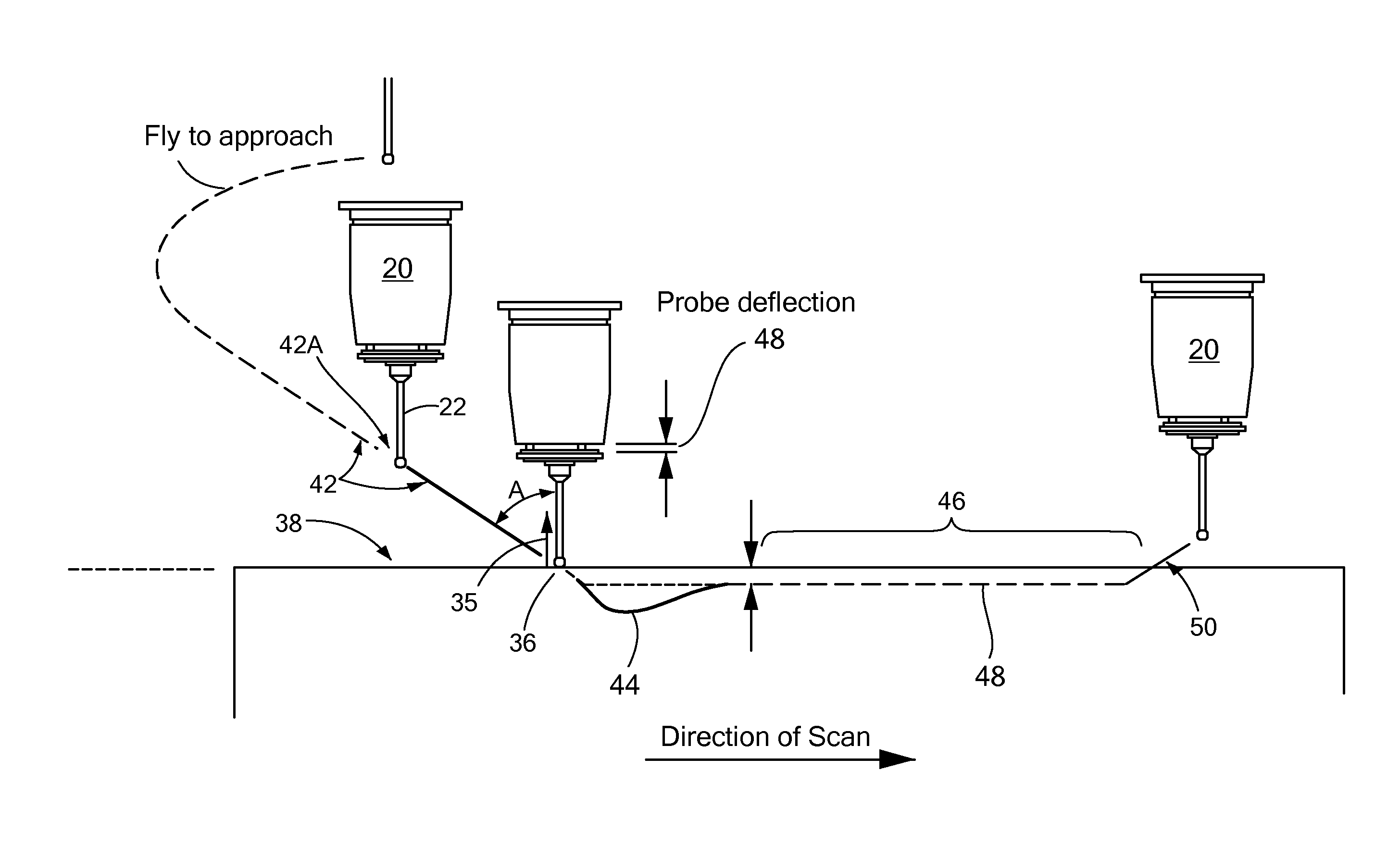
[0007]In accordance with one embodiment of the invention, a method improves surface scanning measure machine speed while minimizing tip touchdown impact on the surface of the object being measured. Specifically, the method controls a surface scanning measuring machine having a probe head with a distal probe tip that contacts the surface of an object to be measured. To that end, the method selects a nominal initial contact point (on the surface) having a normal vector, and then moves the distal probe tip toward the nominal initial contact point along an approach path. The approach path has a generally linear portion that generally linearly extends from the nominal initial contact point to some non-contacting point spaced from the surface. The generally linear portion forms an angle of between about 20 degrees and about 60 degrees with the normal vector.

Problems solved by technology

Both initial and final contact with the surface, however, create a number of performance challenges.
This approach thus reduces throughput, increasing costs.
While attempting to mitigate the hard landing issue, this technique still is time consuming because of the lengthy time it takes to approach the surface.
In addition, the shallow angle makes the settling more challenging.

Method used


Image

  • Method and apparatus for controlling a surface scanning coordinate measuring machine
  • Method and apparatus for controlling a surface scanning coordinate measuring machine
  • Method and apparatus for controlling a surface scanning coordinate measuring machine

Examples


Embodiment Construction

[0029]In illustrative embodiments, a coordinate measuring machine directs the approach of its probe head and tip toward the surface to be measured at an angle of less than about 60 degrees from the nominal surface normal. Accordingly, the entire approach, settling, scanning, and release process can be completed substantially continuously, quickly, and with a minimum risk of a damaging hard impact on the measured surface. Details of illustrative embodiments are discussed below.

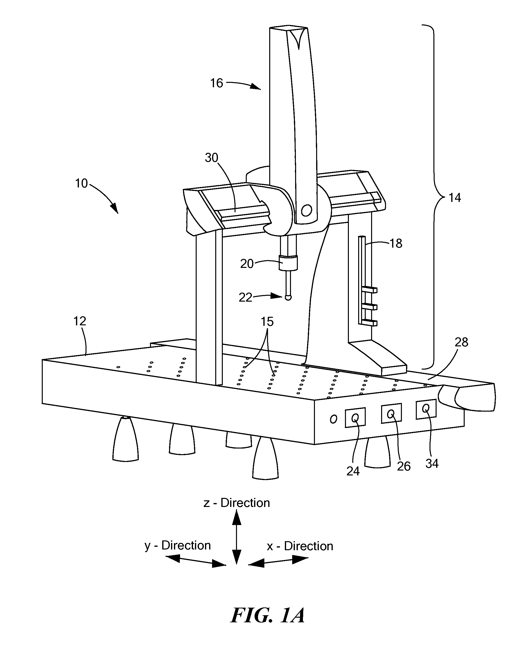
[0030]FIG. 1A schematically shows a coordinate measuring machine (hereinafter “CMM 10”) having logic for implementing illustrative embodiments of the invention. As with other CMMs, the CMM 10 of FIG. 1 has a generally rectangular platform 12 for supporting an object (not shown in FIG. 1) to be scanned, and a scanning apparatus 14 movably connected to the platform 12 for gathering topographical information about the supported object. The platform 12, which can be formed from any of a variety of materials, such a...


PUM


Abstract

A method improves surface scanning measure machine speed while minimizing tip touchdown impact on the surface of the object being measured. Specifically, the method controls a surface scanning measuring machine having a probe head with a distal probe tip that contacts the surface of an object to be measured. To that end, the method selects a nominal initial contact point (on the surface) having a normal vector, and then moves the distal probe tip toward the nominal initial contact point along an approach path. The approach path has a generally linear portion that generally linearly extends from the nominal initial contact point to some non-contacting point spaced from the surface. The generally linear portion forms an angle of between about 20 degrees and about 60 degrees with the normal vector.

Description

PRIORITY[0001]This patent application claims priority from provisional U.S. patent application Ser. No. 61 / 382,126 filed Sep. 13, 2010 entitled, “METHOD FOR CONTROLLING A SURFACE SCANNING COORDINATE MEASURING MACHINE,” and naming Paul Racine as inventor, the disclosure of which is incorporated herein, in its entirety, by reference.FIELD OF THE INVENTION[0002]The invention generally relates to controlling a surface scanning coordinate machine and, more particularly, the invention relates to controlling probe movement of a surface scanning coordinate machine.BACKGROUND OF THE INVENTION[0003]Among other things, coordinate measuring machines (“CMMs,” also known as surface scanning measuring machines) measure unknown surface profiles, or verify the topography of known surfaces. For example, a CMM may measure the topological profile of a propeller to ensure that its surface is appropriately sized and shaped for its specified task (e.g., moving a 24 foot boat at prespecified speeds through...

Claims


Application Information

Patent Timeline
Patent Type & Authority Patents(United States)
IPC IPC(8): G01B5/004G01B5/008G05B19/401G05B19/404G01B21/04
CPCG05B19/401G01B5/008G01B21/04G05B19/404G01B21/047G01B5/004G01B21/045G05B19/19
Inventor RACINE, PAUL P.
Owner HEXAGON TECH CENT GMBH
Learn More