
Electrode Arrangement for Electrical Discharge Machining on an Electrically Non-Conductive Material

a technology of electrical discharge and machining, which is applied in the direction of electrical-based machining electrodes, welding apparatus, manufacturing tools, etc., can solve the problems of standstill of methods and interruption of electrical circuits, and achieve prompt erosion of electrically non-conductive materials and rapid and reliable formation

Inactive Publication Date: 2009-08-13
SIEMENS AG
View PDF12 Cites 9 Cited by
  • Summary
  • Abstract
  • Description
  • Claims
  • Application Information

AI Technical Summary

Benefits of technology

[0007]The object of the present invention is to provide an electrode arrangement which allows a rapid and reliable formation of the additional conductive layer of an electrically conductive substance on the electrically non-conductive material and at the same time a prompt erosion of the electrically non-conductive material.
[0009]A particular advantage of the electrode arrangement according to the invention is that the formation of the additional conductive layer, which consists of the electrically conductive substance, takes place quickly and reliably. As a result, the possible machining speed rises considerably, as compared with the methods described in the prior art. Since the deposition of the electrically conductive substance takes place under optimized conditions, the additional electrically conductive layer has higher stability. This reduces the risk that damage to the layer may lead to an interruption in the electrical circuit and consequently to the standstill of the method.
[0012]Tests have shown, moreover, that an electrode arrangement which consists of a discrete erosion electrode for eroding the electrically non-conductive material and of a discrete deposition electrode for depositing the electrically conductive substance allows a particularly rapid and reliable electrical discharge machining of the electrically non-conductive material.
[0017]In a further embodiment of the invention, the deposition electrode and the erosion electrode are connected firmly to one another. This may be implemented, for example, in that the deposition electrode is applied partially as a coating on the erosion electrode or the erosion electrode is applied partially as a coating on the deposition electrode. The coating may consist, for example of TiN. An electrode arrangement is thereby obtained which can be produced in a simple way and has high inherent stability.
[0019]It may be advantageous if the electrode arrangement has a control unit which controls the movement of the electrodes, in particular, in such a way that the erosion electrode and the deposition electrode are moved toward the electrically non-conductive material with different advances. This makes it possible to allow for the fact that the erosion and deposition processes can proceed at different speeds.
[0021]The method is suitable particularly for electrically non-conductive materials which are applied as a coating to a structural part. This coating may be, for example, a heat insulation layer which, in turn, may consist of fully or partially stabilized zirconium oxide or contain the latter. Corresponding coatings are found on many structural parts, and it is often necessary to drill through these coatings, this being possible quickly and efficiently with the aid of the method according to the invention.

Problems solved by technology

This reduces the risk that damage to the layer may lead to an interruption in the electrical circuit and consequently to the standstill of the method.

Method used


Image

  • Electrode Arrangement for Electrical Discharge Machining on an Electrically Non-Conductive Material
  • Electrode Arrangement for Electrical Discharge Machining on an Electrically Non-Conductive Material
  • Electrode Arrangement for Electrical Discharge Machining on an Electrically Non-Conductive Material

Examples


Embodiment Construction

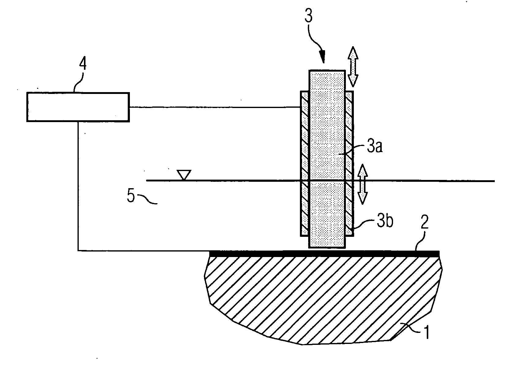
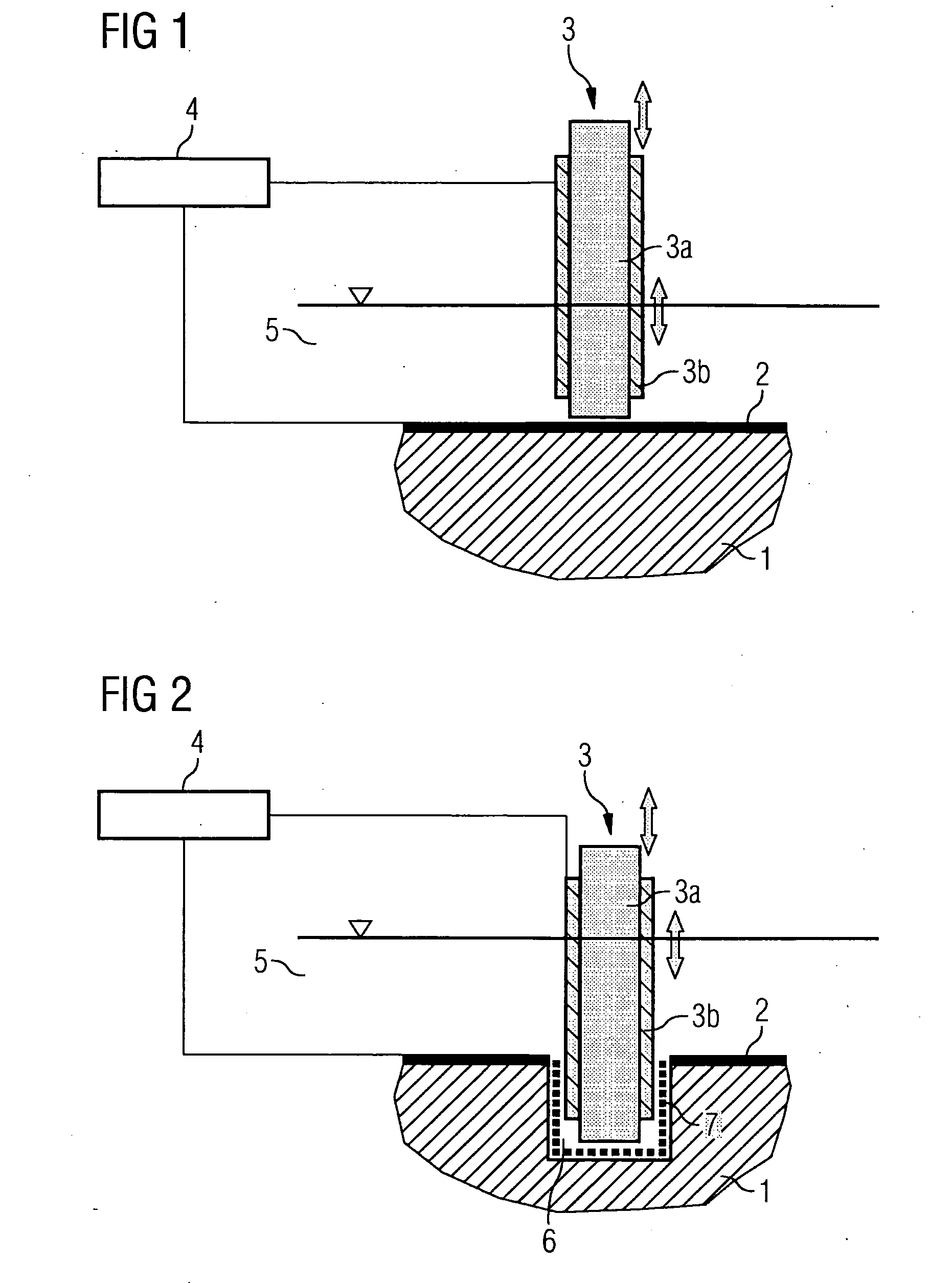
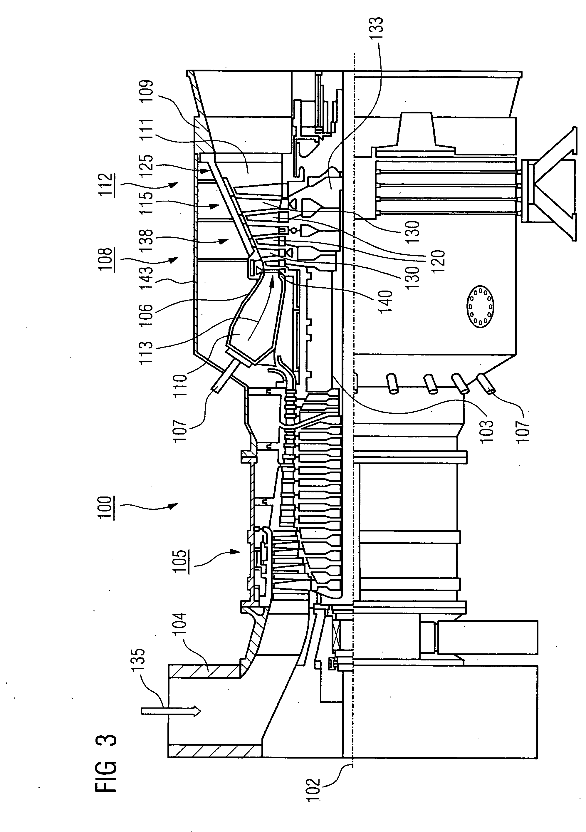
[0029]FIG. 1 shows a diagrammatic illustration of an electrode arrangement according to the invention, the electrode arrangement being illustrated before the machining of an electrically non-conductive material. In the embodiment illustrated, a structural part 1, which consists of an electrically non-conductive ceramic, is to be machined. This may be part of a turbine, such as, for example, a moving blade 120 (FIGS. 3 and 4) or a guide blade 130 (FIGS. 3 and 4). The electrically non-conductive material may also be a coating, for example in the form of a heat insulation layer, and it may consist of fully or partially stabilized zirconium oxide.

[0030]An assisting electrode 2 is applied over a large area as a layer of graphite on the surface of the structural part 1. Various methods known in the prior art are suitable for application, and it may also consist of various metals or of electrically conductive polymers. The assisting electrode 2 is connected electrically conductively to a g...


PUM

PropertyMeasurementUnit
temperatureaaaaaaaaaa
electrically non-conductiveaaaaaaaaaa
electrically conductiveaaaaaaaaaa

Abstract

The invention relates to an electrode arrangement for the electrical discharge machining of an electrically non-conductive material, which comprises a first component for removing the electrically non-conductive material and a second component for depositing an electrically conductive substance on the electrically non-conductive material.

Description

CROSS REFERENCE TO RELATED APPLICATIONS[0001]This application is the US National Stage of International Application No. PCT / EP2007 / 051519, filed Feb. 16, 2007 and claims the benefit thereof. The International application claims the benefits of European application No. 06006139.7 filed Mar. 24, 2006, both of the applications are incorporated by reference herein in their entirety.FIELD OF INVENTION[0002]The invention relates to an electrode arrangement for electrical discharge machining on an electrically non-conductive material and to a method for electrical discharge machining on an electrically non-conductive material, using the electrode arrangement.BACKGROUND OF THE INVENTION[0003]Electrical discharge machining methods for electrically non-conductive materials are known in the prior art. They are employed, inter alia, in order to make bores in components which are provided with a ceramic coating. Thus, for example in turbine blades which have a ceramic heat insulation layer on a ...

Claims


Application Information

Patent Timeline
Patent Type & Authority Applications(United States)
IPC IPC(8): B23H1/04B23H1/00
CPCB23H1/06B23H9/14B23H9/10B23H9/00
Inventor FORSTER, RALFKLEIN, KARSTENLAUDIEN, ULRICHSETTEGAST, SILKESUBRAMANIAN, RAMESH
Owner SIEMENS AG
Learn More