
Multi-track magnetron exhibiting more uniform deposition and reduced rotational asymmetry

a magnetron and multi-track technology, applied in the field of materials sputter deposition, can solve the problems of unsatisfactory techniques, magnetrons have been observed to produce a further deleterious effect, and the shape of the cardiac tube is based on, so as to improve the uniformity of radial erosion

Active Publication Date: 2007-03-06
APPLIED MATERIALS INC
View PDF7 Cites 18 Cited by
  • Summary
  • Abstract
  • Description
  • Claims
  • Application Information

AI Technical Summary

Benefits of technology

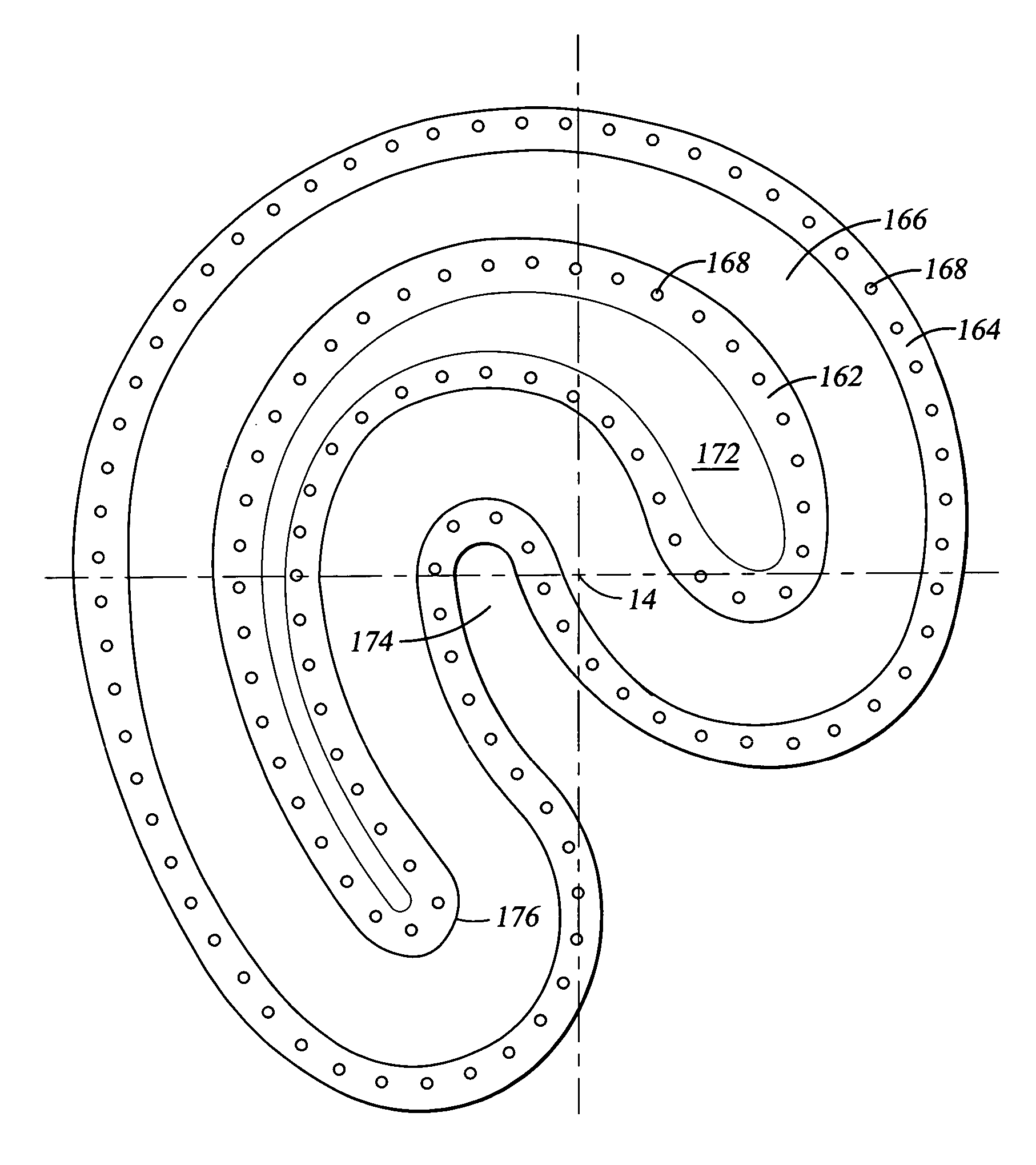
[0020]The design optimization may be based in part upon reduction of azimuthal asymmetry of deposition into alignment mark trenches producing shifts in the marks. Such shifts have been observed to be reduced by the stated design algorithm. The optimization also improves the radial erosion uniformity and deposition uniformity.

Problems solved by technology

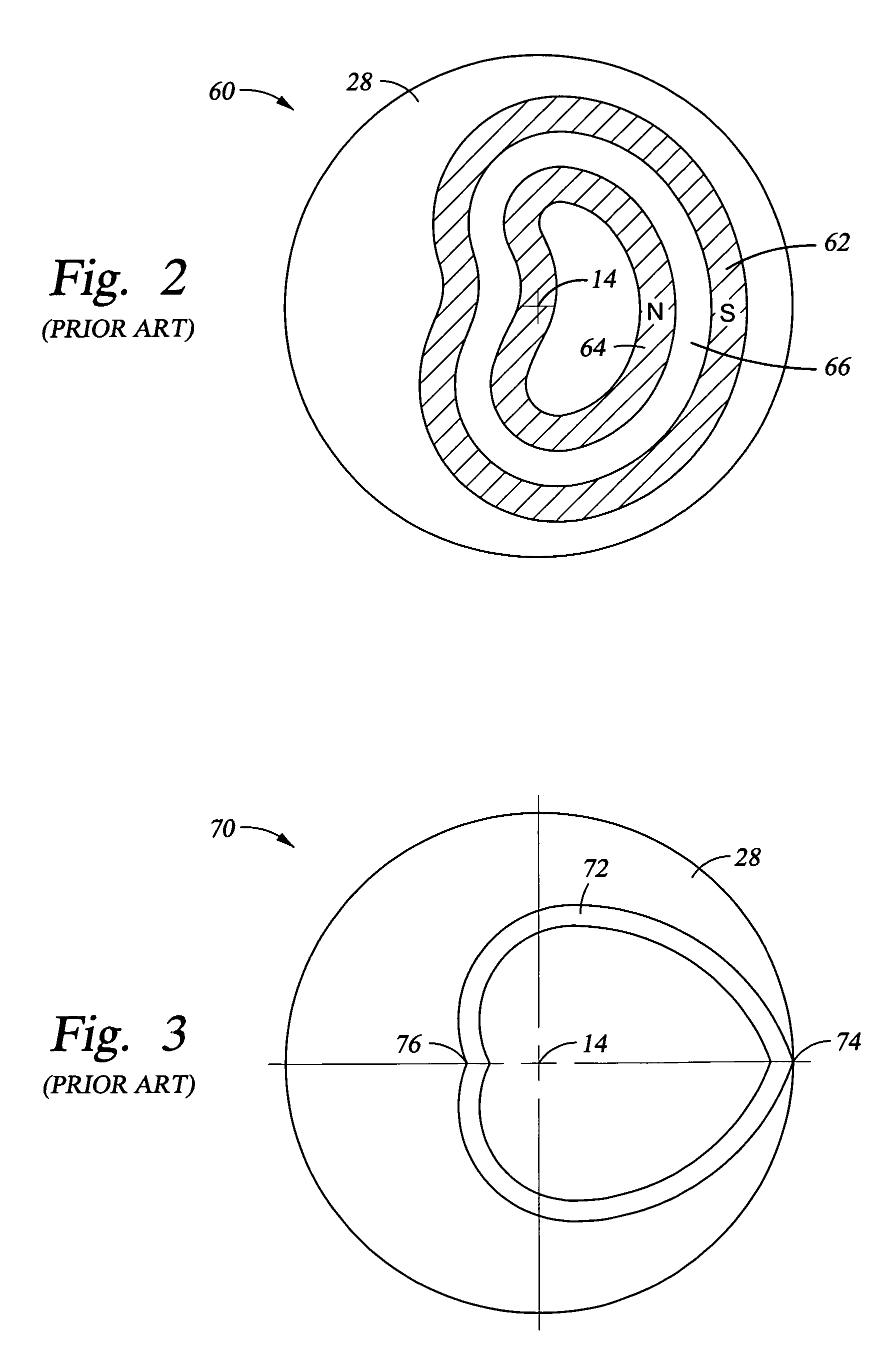
However, Anderson et al. join the ends of two cardioid curves with apparently arbitrary curves of uncertain effect on the erosion profile.
There are two additional problems with the theoretical cardioid shape.
A further problem is that the cardioid shape is based upon a constant erosion profile.
However, these techniques are felt to be unsatisfactory and to not allow sufficient flexibility in the design and operation of the magnetron.
The previously described magnetrons have been observed to produce a further deleterious effect of azimuthal sidewall asymmetry.
Sidewall asymmetry can cause a number of problems, one of which is the drift of alignment indicia used to align the lithography of one level of the integrated circuit with another.
Azimuthal sidewall asymmetry presents a more difficult problem.
Because the magnetron is being rotated along the entire azimuth to supposedly provide azimuthal uniformity, geometrical factors alone are inadequate to explain the azimuthal asymmetry.
Furthermore, the alignment mark shifts arising from azimuthally asymmetric deposition are very difficult to compensate since they vary over the life time of the target.

Method used


Image

  • Multi-track magnetron exhibiting more uniform deposition and reduced rotational asymmetry
  • Multi-track magnetron exhibiting more uniform deposition and reduced rotational asymmetry
  • Multi-track magnetron exhibiting more uniform deposition and reduced rotational asymmetry

Examples


Embodiment Construction

[0037]The invention provides an efficient magnetron shape achieving uniform deposition at low chamber pressure and further provides a design methodology to optimize that shape, a large part of which is easily implemented with modern computer aided design. The flexible design overcomes many of the problems of the magnetrons of the prior art mentioned above.

[0038]It is believed that the azimuthal sidewall asymmetry arises from the Lorentz force. As schematically illustrated in FIG. 7 for the cardioid magnetron 70, a centerline of the gap 72 defines a plasma loop dominating the sputtering of the target. The plasma loop is set up by an annular array of magnets, one magnet pair 110 being shown, creating a magnetic field B extending perpendicularly across the loop. The direction of the magnetic field B is illustrated at two opposed sides of the loop. An argon sputtering ion incident on the target is subject to an electric field E perpendicular to the target as it traverses the relatively ...


PUM

PropertyMeasurementUnit
pressureaaaaaaaaaa
angleaaaaaaaaaa
magnetic polarityaaaaaaaaaa

Abstract

A multi-track magnetron having a convolute shape and asymmetric about the target center about which it rotates. A plasma track is formed as a closed loop between opposed inner and outer magnetic poles, preferably as two or three radially arranged and spirally shaped counter-propagating tracks with respect to the target center and preferably passing over the rotation axis. The pole shape may be optimized to produce a cumulative track length distribution conforming to the function L=arn. After several iterations of computerized optimization, the pole shape may be tested for sputtering uniformity with different distributions of magnets in the fabricated pole pieces. If the uniformity remains unsatisfactory, the design iteration is repeated with a different n value, different number of tracks, or different pole widths. The optimization reduces azimuthal sidewall asymmetry and improves radial deposition uniformity.

Description

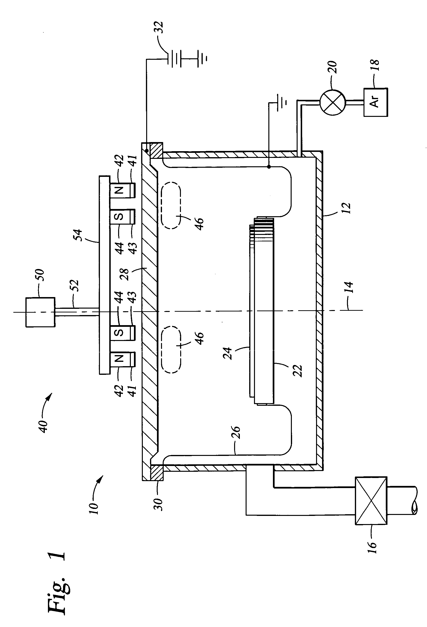
FIELD OF THE INVENTION[0001]The invention relates generally to sputter deposition of materials. In particular, the invention relates to a magnetron creating a magnetic field to enhance sputtering.BACKGROUND ART[0002]Sputtering, alternatively called physical vapor deposition (PVD), is commonly used to deposit layers of metals and related materials in the fabrication of semiconductor integrated circuits and is also used for depositing coatings of materials onto other types of panels. DC magnetron sputtering from conductive targets is the most prevalently used form of sputtering in the commercial fabrication of integrated circuits. As schematically illustrated in the cross-sectional view of FIG. 1, one type of a DC magnetron sputtering chamber 10 includes a vacuum chamber 12 arranged generally symmetrically about a central axis 14. A vacuum pump system 16 pumps the vacuum chamber 12 to a very low base pressure in the range of about 10−6 Torr or even below. However, an argon gas source ...

Claims


Application Information

Patent Timeline
Patent Type & Authority Patents(United States)
IPC IPC(8): C23C14/35
CPCH01J37/3408H01J37/3405C23C14/35
Inventor YANG, HONG S.GUNG, TZA-JINGLEI, JIAN-XINGUO, TED
Owner APPLIED MATERIALS INC
Learn More