Double-sided high-speed gravure coating device and method for lithium battery
A coating device, lithium battery technology, applied in gravure rotary printing machine, printing, rotary printing machine and other directions, can solve the problems of high coating cost and low efficiency, so as to reduce production cost, reduce labor, and improve work efficiency Effect
- Summary
- Abstract
- Description
- Claims
- Application Information
AI Technical Summary
Problems solved by technology
Method used
Image
Examples
Embodiment 1
[0038] In order to overcome the problem of low efficiency of the original coating machine, this embodiment provides a double-sided high-speed gravure coating device for lithium batteries, such as figure 1 As shown, it includes the unwinding mechanism 1, the feeding traction mechanism 2, the front coating mechanism 3, the lower drying box 4, the reverse coating mechanism 5, the upper drying box 6, and the discharging traction mechanism through which the positive and negative materials of the lithium battery pass sequentially. 7 and winding mechanism 8, the described unwinding mechanism 1, feeding traction mechanism 2, front coating mechanism 3, discharging traction mechanism 7 and winding mechanism 8 are arranged in sequence from left to right, and the lower drying box 4 and The upper drying box 6 is distributed parallel up and down, the front coating mechanism 3 and the discharge traction mechanism 7 are located at one end of the lower drying box 4, and the reverse coating mech...
Embodiment 2
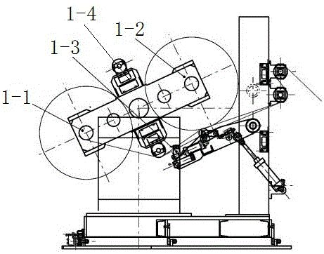
[0041] Such as figure 2 As shown, the present embodiment describes the unwinding mechanism 1 in detail on the basis of Embodiment 1, and the described unwinding mechanism 1 consists of a frame and a first unwinding shaft 1-1 installed on the frame, a second unwinding shaft 1-1, and a second unwinding shaft 1-1. Reel 1-2, unwinding cutter 1-3, automatic rewinding device 1-4, lithium battery positive and negative materials are rolled on the first unwinding reel 1-1, second unwinding reel 1-2, the second One unwinding reel 1-1 and the second unwinding reel 1-2 are installed on the automatic rewinding and unwinding device 1-4, and an unwinding cutter 1-2 is installed next to the first unwinding reel 1-1 or the second unwinding reel 1-2 3.
[0042] The first unwinding shaft 1-1 and the second unwinding shaft 1-2 work alternately. When the first unwinding shaft 1-1 has lighted the material, the unwinding cutter 1-3 cuts the material, and the automatic unwinding device 1-4 Control...
Embodiment 3
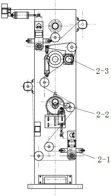
[0044] Such as image 3 As shown, the present embodiment describes in detail the feeding traction mechanism 2 on the basis of Embodiment 1. The described feeding traction mechanism 2 consists of a frame and a tension roller control system 2-1 installed on the frame, Feeding driving mechanism 2-2, traction pressing system 2-3, tension floating roller control system 2-1, feeding driving mechanism 2-2, traction pressing system 2-3 on the frame from bottom to top distributed.
[0045] The tension floating roller control system 2-1, the feeding drive mechanism 2-2, and the traction pressing system 2-3 involved here are all existing mechanisms, such as image 3 shown, and will not be described in detail here. After the lithium battery material (aluminum foil or copper foil) enters the tension roller control system 2-1, it enters the feeding drive mechanism 2-2, and then enters the traction pressing system 2-3 and is pulled out.
PUM
 Abstract
Description
Claims
Application Information
 - R&D
- Intellectual Property
- Life Sciences
- Materials
- Tech Scout
- Unparalleled Data Quality
- Higher Quality Content
- 60% Fewer Hallucinations
Browse by: Latest US Patents, China's latest patents, Technical Efficacy Thesaurus, Application Domain, Technology Topic, Popular Technical Reports.
© 2025 PatSnap. All rights reserved.Legal|Privacy policy|Modern Slavery Act Transparency Statement|Sitemap|About US| Contact US: help@patsnap.com


