Laser machining method, laser machining apparatus, and laser machining program

a laser machining and laser machining technology, applied in the direction of manufacturing tools, data processing applications, welding/soldering/cutting articles, etc., can solve the problems of reducing machining quality, and reducing the accuracy of laser irradiation. the shortest route, the effect of minimizing the variations of the hole diameter

Active Publication Date: 2015-01-22
HITACHI SEIKO LTD
View PDF5 Cites 10 Cited by
  • Summary
  • Abstract
  • Description
  • Claims
  • Application Information

AI Technical Summary

Benefits of technology

[0012]This minimizes the variations in hole diameter due to heating effects even in the case where the shortest machining route is set.
[0013]The present inv...

Problems solved by technology

Thus, there has been a possibility that when an immediately adjacent position is irradiated by laser, the diameter of the adjacent hole becomes larger than a predetermined hole diameter due to cu...

Method used


Image

  • Laser machining method, laser machining apparatus, and laser machining program
  • Laser machining method, laser machining apparatus, and laser machining program
  • Laser machining method, laser machining apparatus, and laser machining program

Examples


Embodiment Construction

[0024]In the following detailed description, for purpose of explanation, numerous specific details are set forth in order to provide a thorough understanding of the disclosed embodiments. It will be apparent, however, that one or more embodiments may be practiced without these specific details. In other instances, well-known structures and devices are schematically shown in order to simplify the drawing.

[0025]Hereinafter, an embodiment of the present invention will be described with reference to the accompanying drawings.

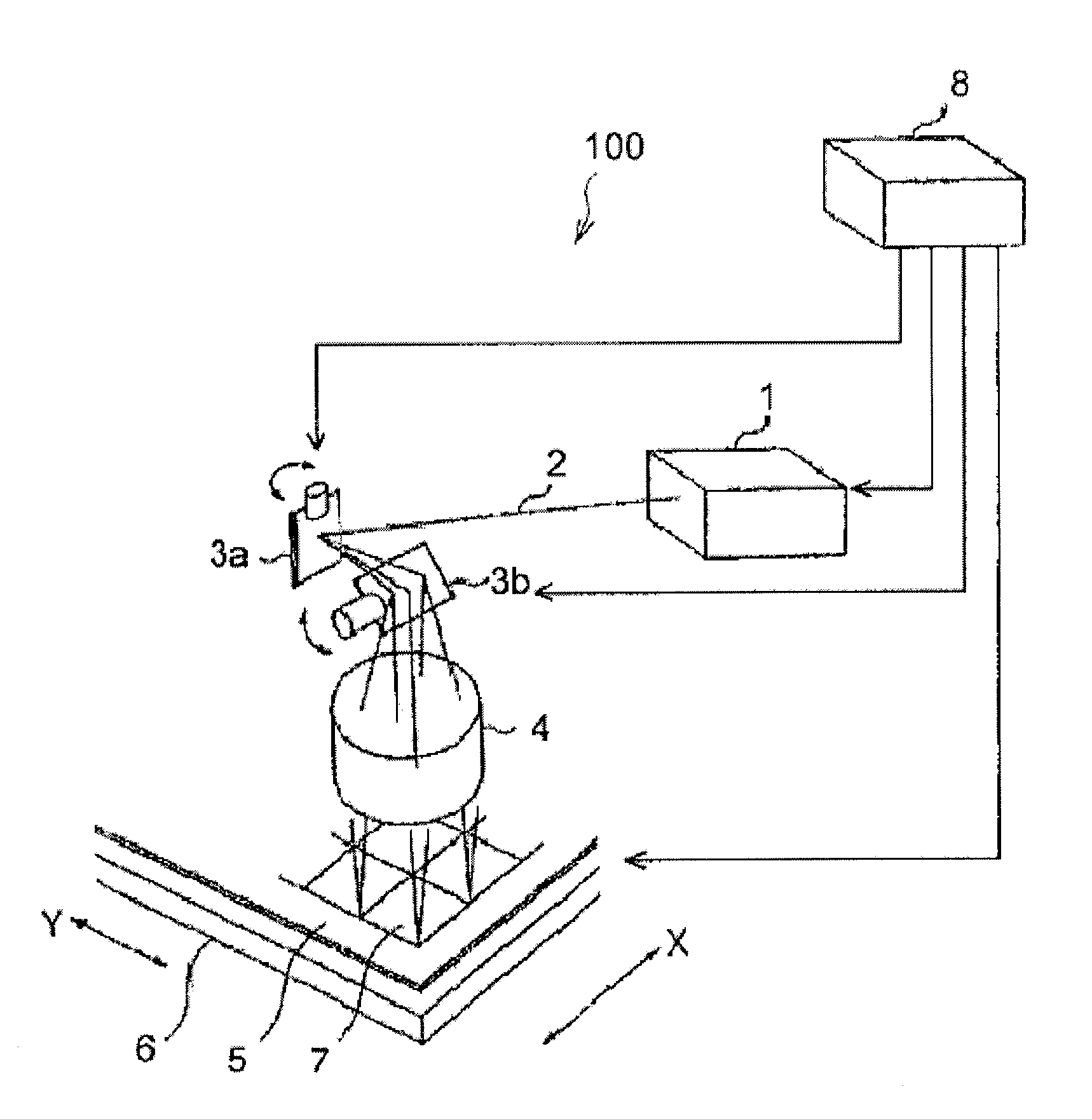
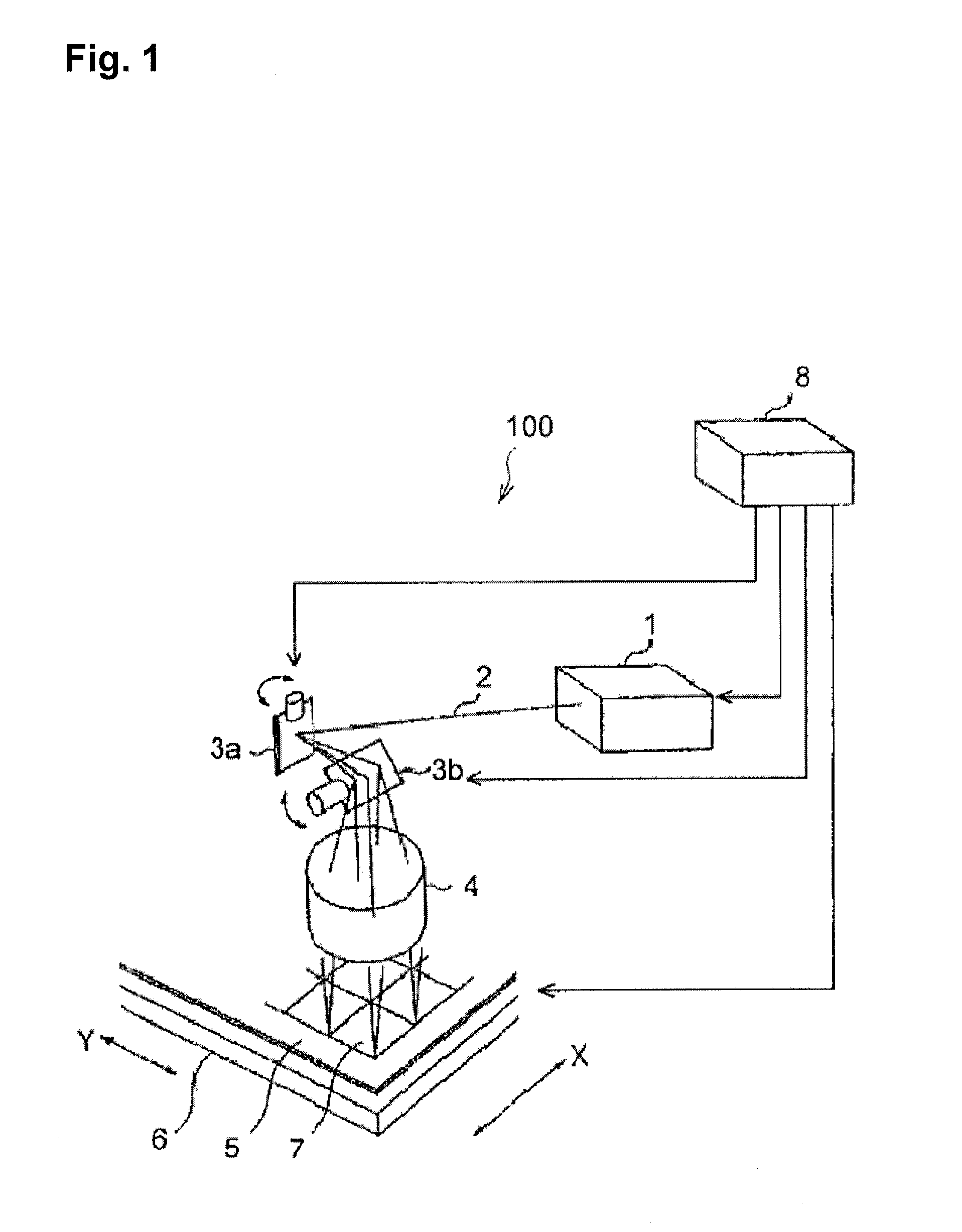
[0026]FIG. 1 is a schematic diagram illustrating a laser machining apparatus according to the embodiment of the present invention. In this diagram, a laser machining apparatus 100 basically includes a laser beam source 1, first and second galvanometer mirrors 3a and 3b, an fθ lens 4, an XY table 6, and a control device 8.

[0027]In the laser machining apparatus 100 of such configuration, a laser beam is emitted from the laser beam source 1, and scanned onto a printed ...


PUM


Abstract

Variation in hole diameter due to heating effects is minimized even if the shortest machining route is set, and machining quality is improved. A printed circuit board to be scanned by a laser beam is divided into a plurality of scan areas (S1). An order of drilling within the scan area is sorted to obtain a scanning route with the shortest distance (S2). The order of the (N+1)th hole and the (N+2)th hole is swapped in each scanning area if it is determined that the distance between the Nth hole and the (N+1)th hole (here, N is an integer in a range of 1≦N≦“the maximum number of holes to be drilled in the area”−1″) is less than a predetermined threshold value, and that N+1 is not correspond to the maximum number of holes to be drilled in the scanning area (S3). The scanning area is machined and then machining each scanning area, specifically in machining the (N+1)th hole, after pausing for a period of a predetermined heat dissipation time if it is determined that the distance between the N-th hole and the (N+1)th hole swapped is less than the predetermined threshold value. Subsequently, machining is performed (S4).

Description

CROSS-REFERENCE TO RELATED APPLICATION[0001]This application is based on Japanese Patent Application No. 2011-250753 filed with the Japan Patent Office on Nov. 16, 2011, the entire content of which is hereby incorporated by reference.BACKGROUND[0002]1. Technical Field[0003]The present invention relates to a laser machining method, a laser machining apparatus, and a laser machining program, more specifically, relates to a laser machining method and a laser machining apparatus for setting an optimum machining route for drilling a plurality of holes in a substrate by irradiation with a laser beam, and relates to a laser machining program executed by this laser machining apparatus.[0004]2. Related Art[0005]Examples of such techniques are found in JP-A-2001-195112 (hereinafter referred to as Patent Document 1) and JP-A-2008-049398 (hereinafter referred to as Patent Document 2). In Patent Document 1, a laser drilling route determination method for shortening computation time that is requi...

Claims


Application Information

Patent Timeline
IPC IPC(8): H05K3/00G06Q10/04B23K26/38
CPCG06Q10/043B23K26/381H05K3/0035B23K26/0648B23K26/0807B23K26/0853B23K26/4075H05K3/0005H05K3/0008H05K3/0026B23K26/02B23K26/04B23K26/082B23K26/38B23K26/382B23K26/40B23K2103/50H05K3/00
Inventor OZAWA, HIDEKATSU
Owner HITACHI SEIKO LTD
Why Eureka
Try Eureka