Electric discharge machining apparatus

a technology of machining apparatus and electric discharge, which is applied in the direction of electrode supporting device, manufacturing tools, and vibration holders of electric devices, etc., can solve the problems of reducing machining accuracy, increasing the weight of the drive shaft, and reducing the speed or speed of machining, so as to improve the responsive drivability and improve the machining speed

Inactive Publication Date: 2005-01-27
MITSUBISHI ELECTRIC CORP
View PDF4 Cites 9 Cited by
  • Summary
  • Abstract
  • Description
  • Claims
  • Application Information

AI Technical Summary

Benefits of technology

[0008] The present invention is intended to obviate the above-mentioned problems, and has for its object to provide an electric discharge machining apparatus having improved responsive drivability as well as improved machining speed.
[0009] Another object of the present invention is to provide an electric discharge machining apparatus in which an electrode driving device is prevented from thermal deformation due to the heat generation of electromagnetic portions, thereby making it possible to perform stable attraction control on the electromagnetic portions.
[0011] In the electric discharge machining apparatus according to the present invention, a mechanism for rotating the tool electrode is separated from the electrode driving device, and hence the weight of the drive shaft is greatly reduced, whereby fast responsive drivability of the tool electrode can be achieved.

Problems solved by technology

As a result, the gross weight of the drive shaft is increased, so high-speed or fast responsive drivability of the tool electrode might sometimes be impaired, resulting in a problem that the rapidity or fastness of the machining speed is reduced.
However, the amount of heat generated in the electromagnetic portions increases in accordance with the increasing current supplied, as a consequence of which the electrode driving device might sometimes be caused to thermally expand depending upon the amount of heat thus generated, giving rise to another problem that machining accuracy is reduced.

Method used


Image

  • Electric discharge machining apparatus
  • Electric discharge machining apparatus
  • Electric discharge machining apparatus

Examples


embodiment 1

[0024] Embodiment 1

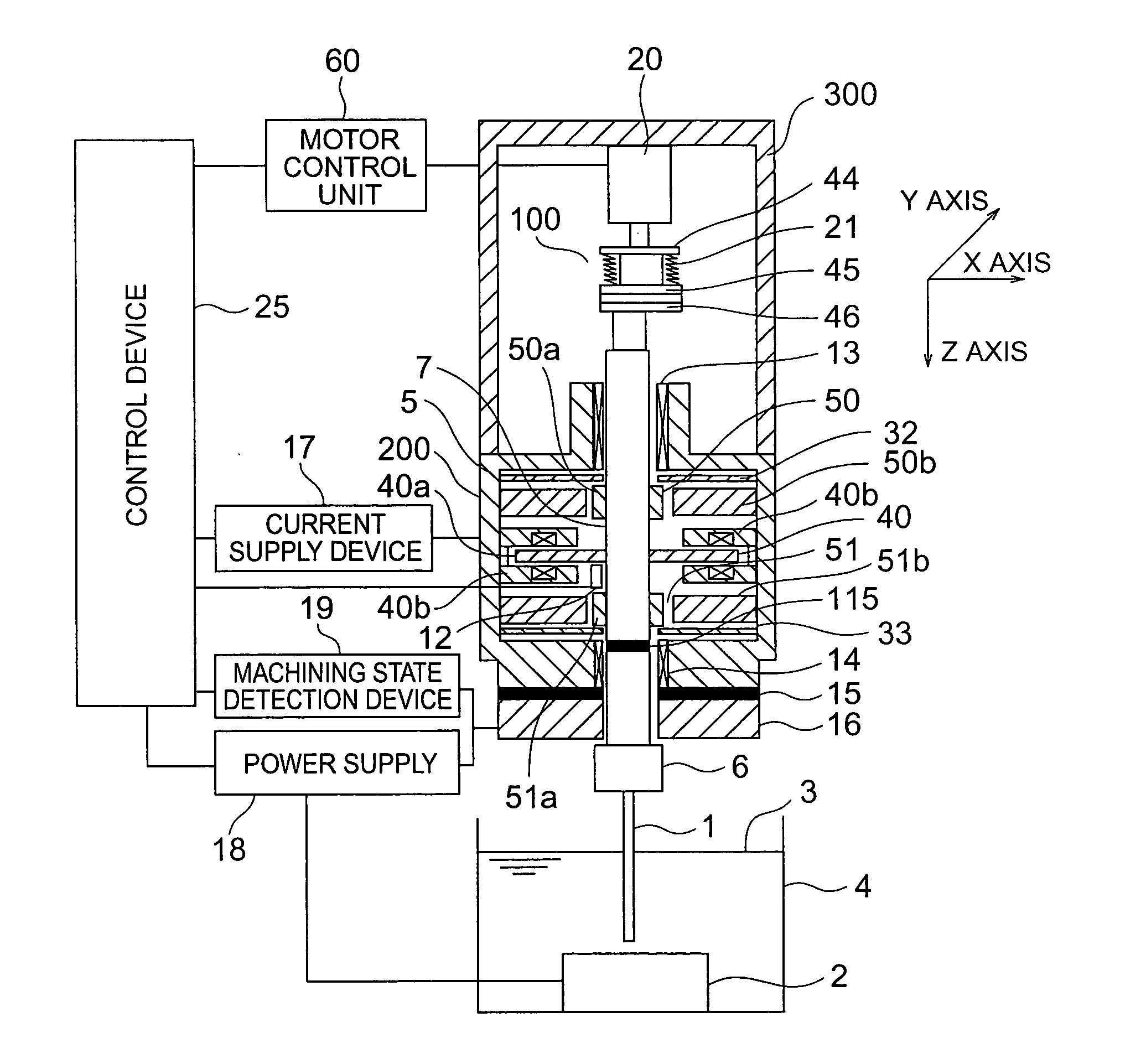
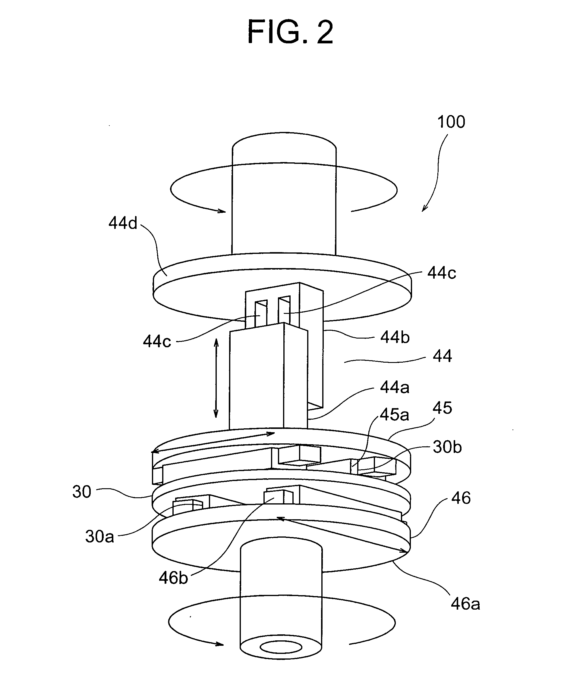
[0025]FIG. 1 is a constructional view of an electric discharge machining apparatus according to a first embodiment of the present invention.

[0026] This electric discharge machining apparatus includes: a tool electrode 1 having its tip end directed to a work piece 2 disposed on the bottom of a machining tank 4 in which a working fluid in the form of an oil 3; a drive shaft 7 fixedly attached to the tool electrode 1 through an electrode mounting section 6 with an insulating plate 115 being interposed at an intermediate portion thereof; an electrode driving device 5 that drives the tool electrode 1 through the drive shaft 7; a feeder system 16 fixedly secured to the electrode driving device 5 through an insulating plate 15 formed of a ceramic disc for supplying electric power to the electrode driving device 5; a coupling 100 connected with the drive shaft 7 and being movable in three directions including a Z-axis direction (a top and bottom direction with respect to...

embodiment 2

[0049] Embodiment 2

[0050]FIG. 3 is a constructional view of an electric discharge machining apparatus according to a second embodiment of the present invention.

[0051] This second embodiment is similar in construction to the first embodiment excluding the following: that is, the construction of a coupling 150 is different from the coupling 100 of the first embodiment, and the spring 21 of the first embodiment is omitted.

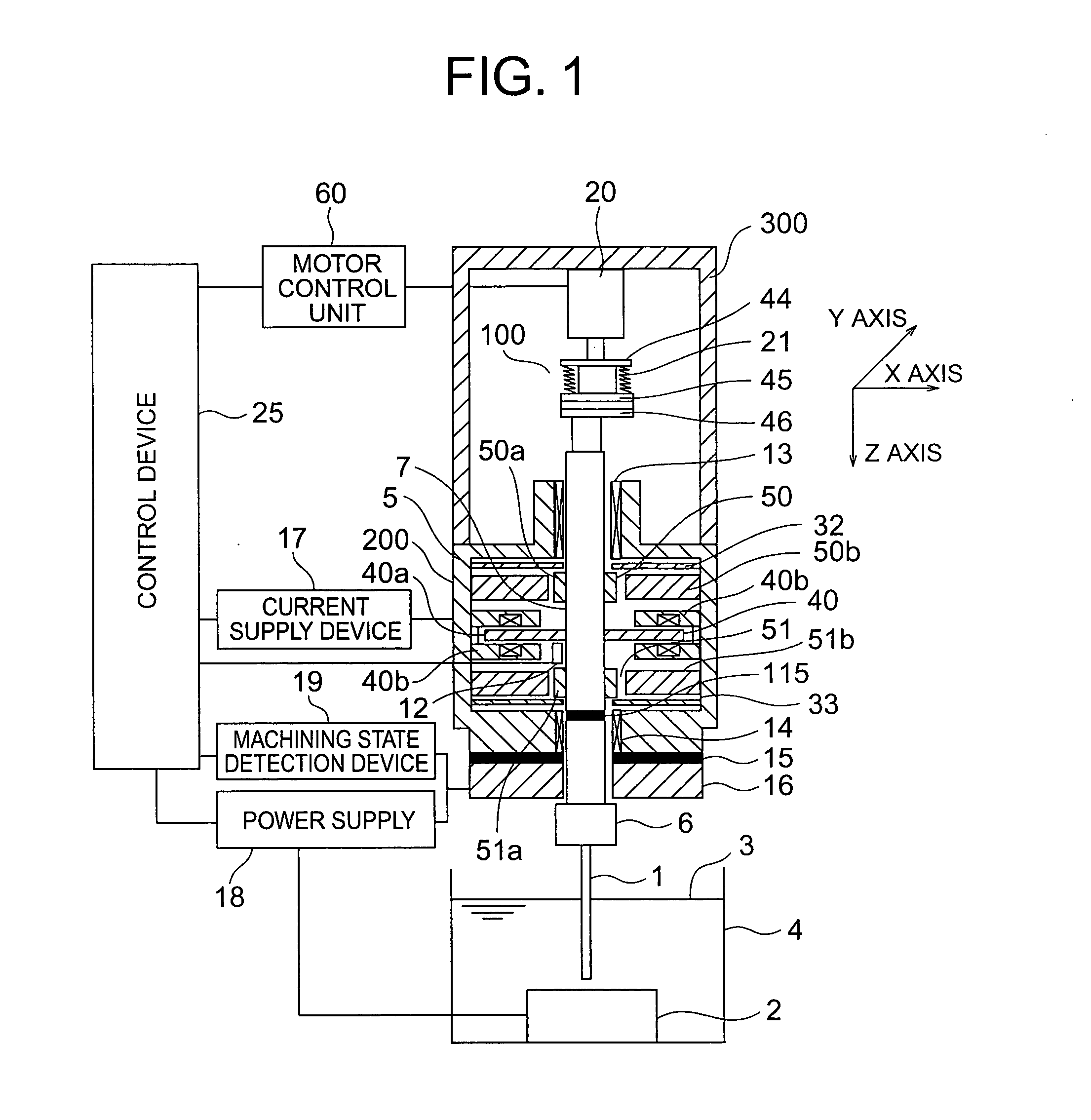
[0052] In this second embodiment, the coupling 150 is constructed as follows. The Z direction slider 44 is mounted on an upper end portion of the drive shaft 7, and the Y direction slider 45 is mounted on the Z direction slider 44, and the X direction slider 46 is mounted on the Y direction slider 45 through the intermediate disc portion 30. The electric motor 20 has its rotation shaft connected with the X direction slider 46.

[0053] The coupling 150 is constructed such that the arrangement of the Z direction slider 44 and the X direction slider 46 is reversed in co...

embodiment 3

[0055] Embodiment 3

[0056]FIG. 4 is a constructional view of an electric discharge machining apparatus according to a third embodiment of the present invention.

[0057] In this third embodiment, a rotational position scale 151 is mounted on the Z direction slider 44 at a location between the Z direction slider 44 and the electric motor 20 with its central axis being in coincidence with the axis of rotation of the electric motor 20, and a rotational position scale reader 152 is mounted on the electric motor 20. Here, note that the rotational position scale 151 and the rotational position scale reader 152 together constitute a rotation detection unit for detecting rotation information of the drive shaft 7.

[0058] The construction of this third embodiment other than the above is the same as that of the electric discharge machining apparatus according to the first embodiment.

[0059] In this third embodiment, the rotational position scale reader 152 reads out the current angle or angular v...


PUM

PropertyMeasurementUnit
speedaaaaaaaaaa
thicknessaaaaaaaaaa
widthaaaaaaaaaa

Abstract

An electric discharge machining apparatus has improved responsive drivability and improved machining speed. A tool electrode has a tip end directed toward a work piece, a voltage applied between the tool electrode and the work piece generating a discharge. A drive shaft is connected with the tool electrode. An electrode driving device has magnetic bearings for moving the drive shaft in three directions including a Z-axis direction which is an axial direction of the drive shaft, a Y-axis direction perpendicularly crossing the Z-axis direction, and an X-axis direction perpendicularly crossing the Y-axis direction and Z-axis direction, by supplying electric current to electromagnetic portions to control magnetic attraction. A movable coupling is connected with an end of the drive shaft and is movable in the three directions. An electric motor is connected with an end of the coupling for rotating the drive shaft through the coupling.

Description

BACKGROUND OF THE INVENTION [0001] 1. Field of the Invention [0002] The present invention relates to an electric discharge machining apparatus that machines a work piece by means of an electric discharge generated by application of a voltage between a tool electrode and the work piece. [0003] 2. Description of the Related Art [0004] A conventional electric discharge machining apparatus has hitherto been known in which a tool electrode is moved in an X-axis, a Y-axis and a Z-axis direction by using an electrode driving device with a magnetic bearing mechanism being applied to driving the tool electrode for electric discharge machining (for example, see a first patent document: International Publication No. 02 / 024389A1). [0005] In this conventional electric discharge machining apparatus, an electric motor by which the tool electrode is driven to rotate is incorporated in the electrode driving device. [0006] In the electric discharge machining apparatus, however, the tool electrode is ...

Claims


Application Information

Patent Timeline
Patent Type & Authority Applications(United States)
IPC IPC(8): B23H7/26B23H7/28B23H7/30
CPCB23H7/26B23H7/30B23H7/28B23H7/265
Inventor MIYAKE, HIDETAKAIMAI, YOSHIHITONAKAGAWA, TAKAYUKI
Owner MITSUBISHI ELECTRIC CORP
Why Eureka
Try Eureka