System and method for incremental forming

a technology of incremental forming and incremental forming, which is applied in the direction of metal rolling arrangement, manufacturing tools, shaping tools, etc., can solve the problems of inflexible process, low cost of low-volume sheet metal components, and costly sets of dies, which are not well suited to mass production and prototyping needs, and achieve low cost and flexible, high-quality, and high-quality results

Active Publication Date: 2015-12-29
PENN STATE RES FOUND +1
View PDF24 Cites 2 Cited by
  • Summary
  • Abstract
  • Description
  • Claims
  • Application Information

AI Technical Summary

Benefits of technology

[0009]Double-sided incremental forming (see FIG. 1B) is a more flexible, lower cost method of sheet metal forming which seeks to introduce rapid and simple low volume sheet metal production. In one embodiment, a system (e.g., the system 300 shown in FIG. 2) capable of executing this manufacturing process is provided. In some embodiments, a system may be capable of accurately positioning metal forming tools over an area of about 10 inches by about 10 inches within about 0.002 inches, under forming loads required for sheet metal aluminum, magnesium, steel, alloys, and the like. The system may be controlled using one or more methods, processes, techniques, software systems, and the like, such as those set forth in the '666 Application, '951 Application, '034 Application, and '598 Application.
[0011]Double-sided incremental forming utilizes two opposing tools to deform and support a workpiece such as a sheet of metal, generally resulting in sheet deformation only where desired (see FIG. 1B). Thus, costly dies may be removed, and the benefits of using only non-specific tools can be fully realized. For example, a tool having a generally hemispheric head may be used in a variety of applications to produce a wide variety of shapes or features, in contrast to particular dies limited to specific applications. Various embodiments of systems and methods described herein may be capable of executing double-sided incremental forming in a highly accurate manner, while remaining low cost and flexible, and also introducing new improvements to the forming process.
[0012]Currently, few other prototype machines capable of double-sided incremental forming (DSIF) are known to Applicants to exist. The design of such machines generally heavily relied on components retrofitted to meet the demands of a DSIF machine. At least one embodiment of the system disclosed herein is particularly suited to the demands of double-sided incremental forming, while surpassing the capabilities of these existing machines, and remaining relatively low cost.
[0016]One or more technical effects of at least one embodiment include reduced costs for forming operations (e.g., low production forming), improved forming at reduced forming forces, improved control of forming operations, reduced reliance upon application specific tooling, increased utility of non-specific tooling across a variety of forming applications, improved mobility of forming equipment, and / or improved user friendliness of forming equipment or processes.

Problems solved by technology

Currently, low volume production of sheet metal components is a relatively high cost, inflexible process, requiring costly sets of dies, typically made of cast steel.
These dies, while well suited to mass production, are poorly matched to relatively low volume production and prototyping needs.
Die sets can cost over $1 million per set, can be difficult to move, and / or costly to modify if the final required geometry of parts is not met.
However, complications still exist in the form of unwanted sheet bending and deformation.
This has been partially addressed with partial and full dies implemented on the opposing side of the forming tool to create a support structure; however, use of such partial or full dies re-introduces the high costs and low flexibility of a die.

Method used


Image

  • System and method for incremental forming
  • System and method for incremental forming
  • System and method for incremental forming

Examples


Embodiment Construction

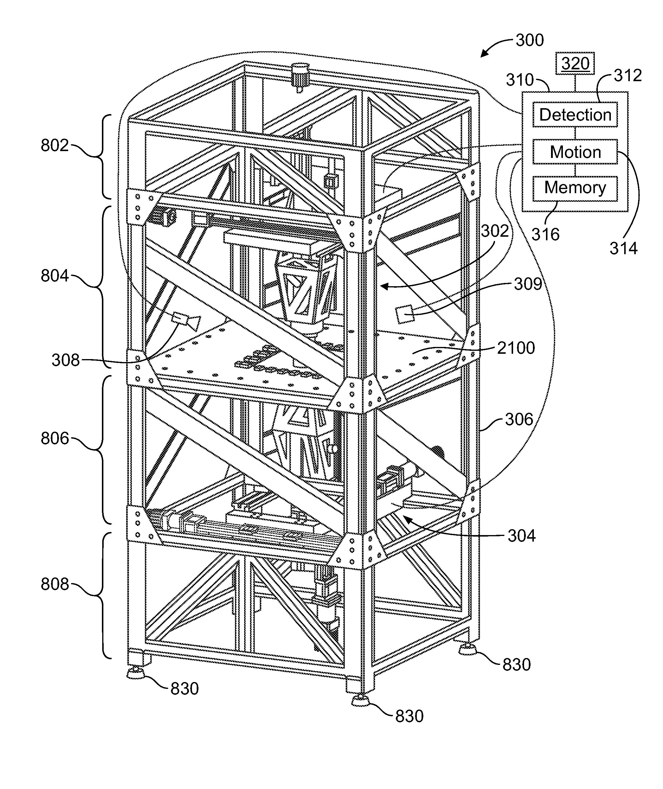
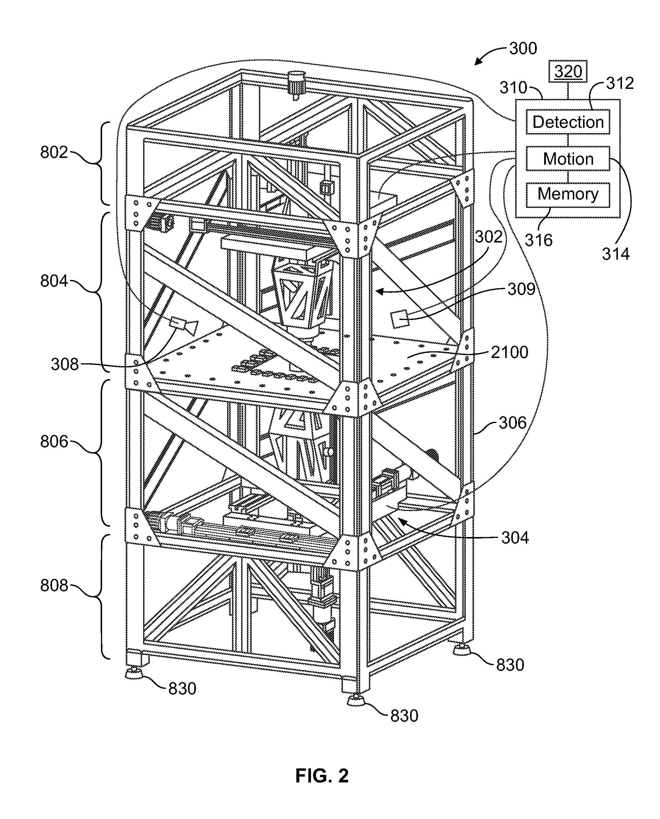
[0029]FIG. 2 is a perspective view of one embodiment of an incremental forming system 300. FIG. 3 is an exploded perspective view of one embodiment of a gantry-style axis assembly 400 of the system 300 in accordance with one embodiment. FIG. 4 is a perspective view of the axis assembly 400 shown in FIG. 3. As seen in FIG. 2, the system 300 can include a top axis assembly 302 that includes an axis assembly 400 and a bottom axis assembly 304 that includes another axis assembly 400.

[0030]In the embodiment depicted in FIG. 2, the system 300 includes a top tool positioning assembly 302, a bottom tool positioning assembly 304, a frame 306, a thermal imaging camera 308, a heat treatment module 309, and a control module 310, and a blankholder frame 2100. The top tool positioning assembly 302 and the bottom tool positioning assembly 304 are configured to secure forming tools on opposing sides of a workpiece held in the blankholder frame 2100, for example, during a double-sided incremental fo...


PUM

PropertyMeasurementUnit
heightaaaaaaaaaa
depthaaaaaaaaaa
widthaaaaaaaaaa

Abstract

A system includes a frame configured to hold a workpiece and first and second tool positioning assemblies configured to be opposed to each other on opposite sides of the workpiece. The first and second tool positioning assemblies each include a toolholder configured to secure a tool to the tool positioning assembly, a first axis assembly, a second axis assembly, and a third axis assembly. The first, second, and third axis assemblies are each configured to articulate the toolholder along a respective axis. Each axis assembly includes first and second guides extending generally parallel to the corresponding axis and disposed on opposing sides of the toolholder with respect to the corresponding axis. Each axis assembly includes first and second carriages articulable along the first and second guides of the axis assembly, respectively, in the direction of the corresponding axis.

Description

CROSS-REFERENCE TO RELATED APPLICATIONS[0001]This application claims priority to U.S. Provisional Application No. 61 / 555,951, which was filed on 4 Nov. 2011, and is entitled “System And Method For Incremental Forming” (the “'951 Application”); U.S. Provisional Application No. 61 / 612,034, which was filed on 16 Mar. 2012, and is entitled “System And Method For Accumulative Double-sided Incremental Forming” (the “'034 Application”); and U.S. Provisional Application No. 61 / 642,598, which was filed on 4 May 2012, and is entitled “System And Method For Accumulative Double-sided Incremental Forming” (the “'598 Application”).[0002]This application also is related to U.S. Nonprovisional application Ser. No. 13 / 654,071, which was filed on 17 Oct. 2012, and is entitled “System And Method For Accumulative Double-sided Incremental Forming” (referred to herein as the “'071 Application”) and U.S. Provisional Application Ser. No. 61 / 550,666, which was filed on 24 Oct. 2011, and is entitled “System ...

Claims


Application Information

Patent Timeline
Patent Type & Authority Patents(United States)
IPC IPC(8): B21B31/00B21D31/00
CPCB21D31/005B21D37/16
Inventor BELTRAN, MICHAELCAO, JIANROTH, JOHN T.
Owner PENN STATE RES FOUND
Why Eureka
Try Eureka