Modular rail thrust block system

a technology of thrust block and module rail, which is applied in the direction of weapons, butts, weapon components, etc., can solve the problems of rail and accessory movemen

Active Publication Date: 2015-12-29
BATTAGLIA VINCENT P
View PDF11 Cites 13 Cited by
  • Summary
  • Abstract
  • Description
  • Claims
  • Application Information

AI Technical Summary

Benefits of technology

[0018]Another aspect of the invention is directed to a shroud for a firearm barrel having on an interior surface thereof

Problems solved by technology

During recoil, the rail and accessory are subject to mov

Method used


Image

  • Modular rail thrust block system
  • Modular rail thrust block system
  • Modular rail thrust block system

Examples


Embodiment Construction

)

[0028]In describing the preferred embodiment of the present invention, reference will be made herein to FIGS. 1-8 of the drawings in which like numerals refer to like features of the invention.

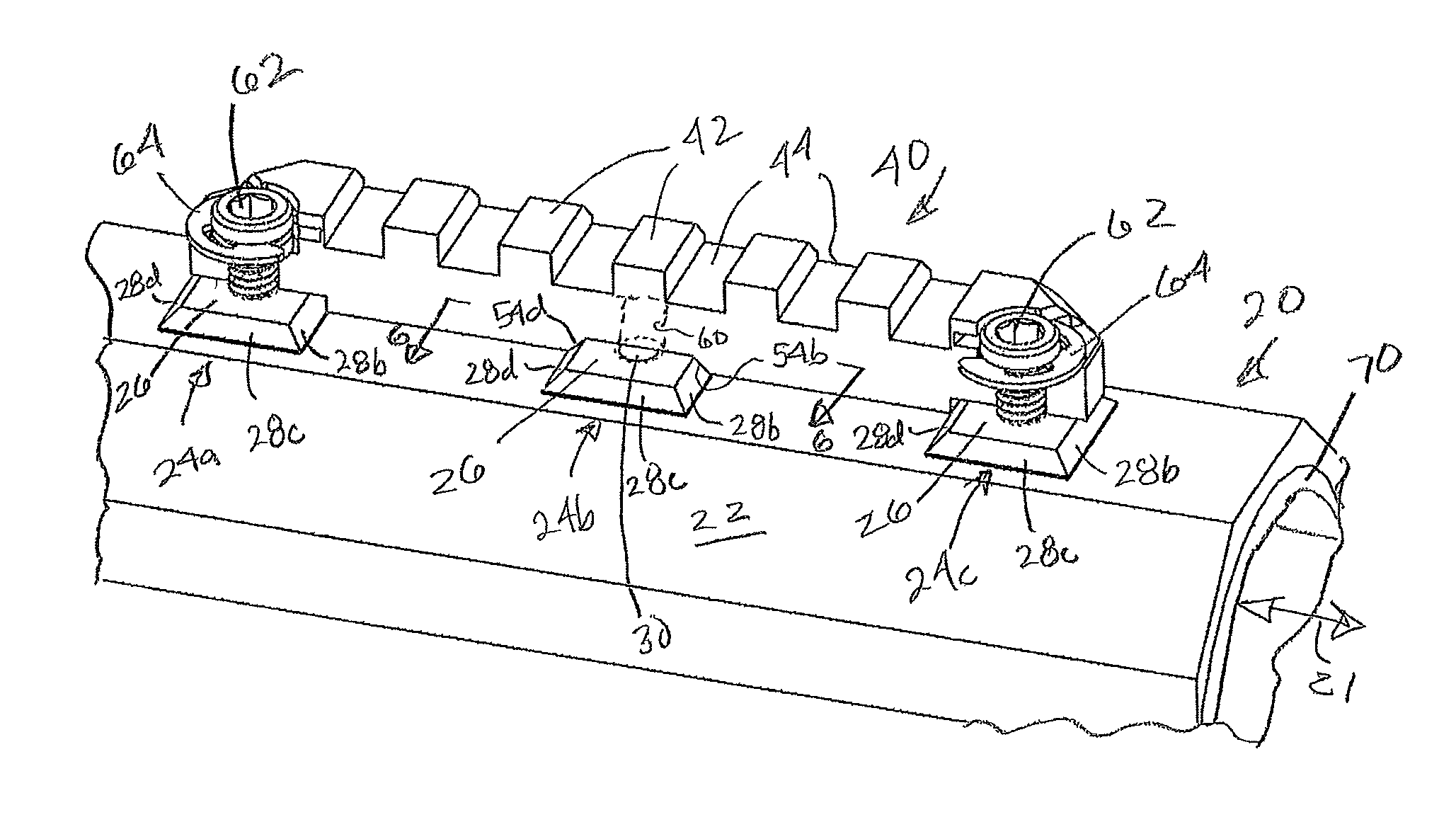
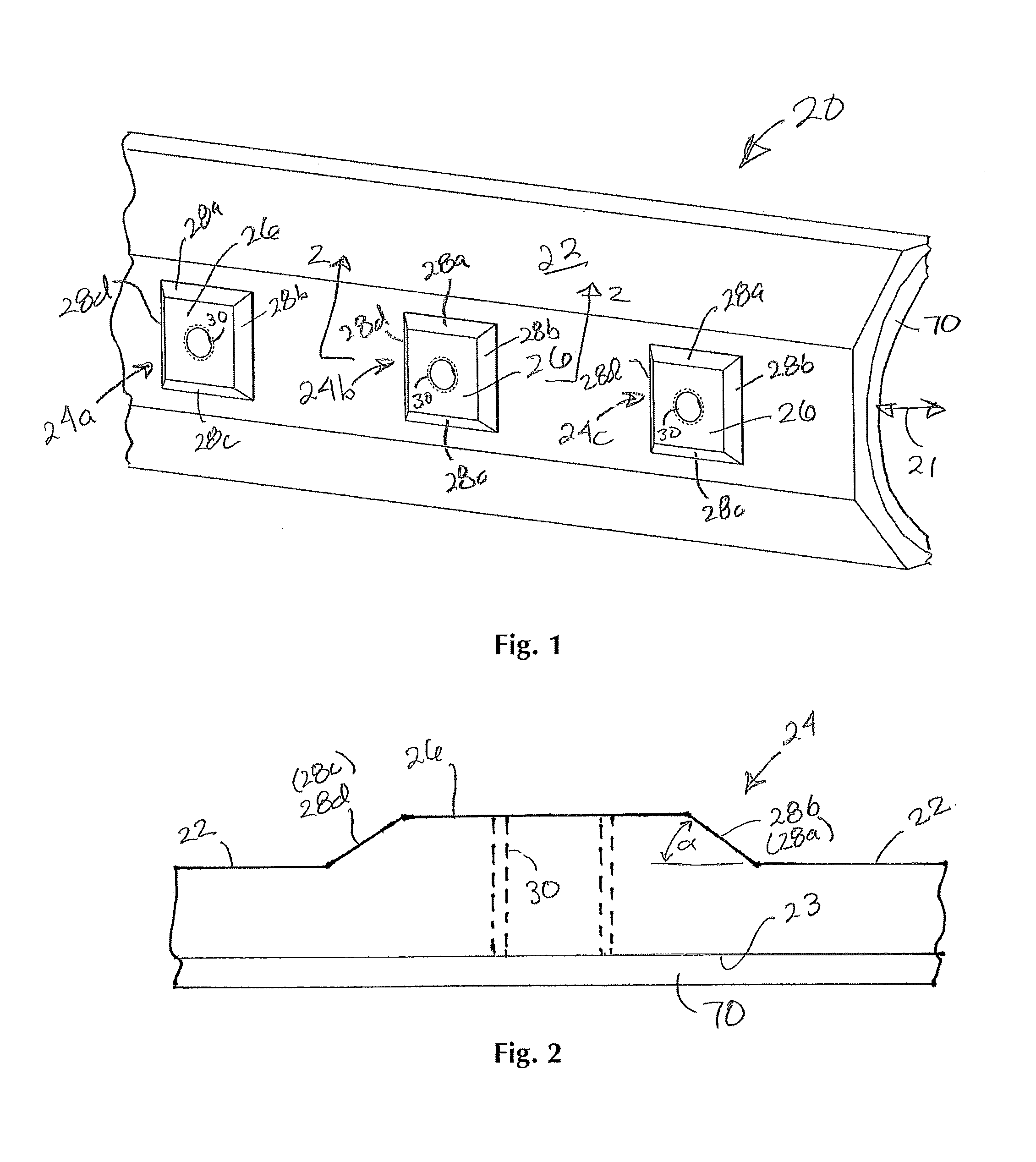
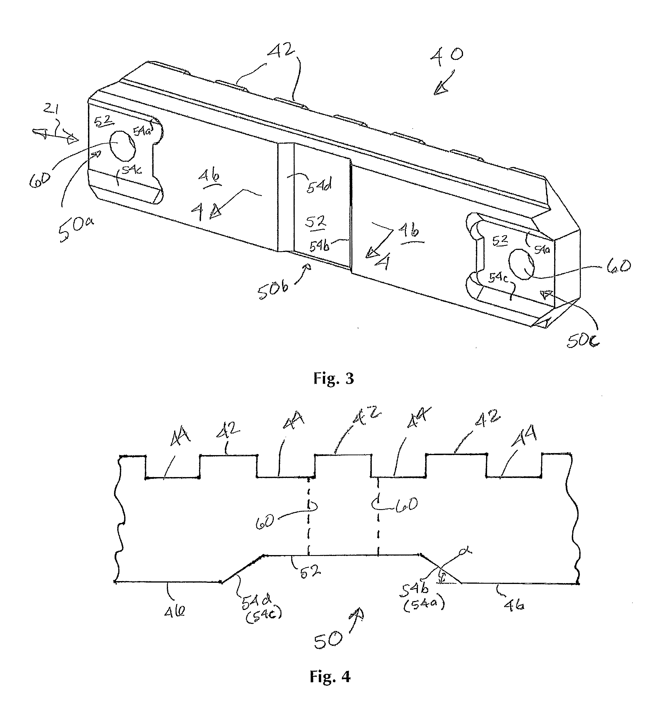
[0029]The present invention provides a rifle fore end or shroud with multiple square projections with beveled walls, each housing a tap hole to receive a standard fastener, and to facilitate and receive a modular Picatinny rail of various lengths. A square projection secures and fastens the modular Picatinny rail in axes in the direction of and normal to the rifle bore, thereby isolating movement and recoil in a multi-axis fashion.

[0030]FIGS. 1 and 5 show an otherwise standard shroud or fore end piece 20 that may function as a forestock for a rifle, to be attached to and over and / or around the barrel. The shroud may also be attached to the barrel of a revolver, or on the underside of a semi-automatic pistol frame. Shroud 20 may be in the form of a tube to fit over all or part of the barrel of...


PUM


Abstract

A rail mounting system for a firearm includes a shroud on the fore end having a plurality of spaced rectangular pads with raised, rectangular top surfaces and opposed sloping sides forming an opposed pair of side walls that intersect with the shroud surface at an acute angle. The rail mounting system also includes a mounting rail having spaced apart relief sections conforming to the locations of the pads with recessed rectangular relief bottoms and opposed sloping sides forming an opposed pair of angled side walls at the same angle as the pad side walls. The side walls of the pads and relief sections are in contact with each other along at least some of their vertical distances. The pad top is spaced from the relief bottom and the shroud surface is spaced from the rail underside.

Description

[0001]This application claims priority to U.S. application No. 61 / 974,121 filed on Apr. 2, 2014.BACKGROUND OF THE INVENTION[0002]1. Field of the Invention[0003]The present invention is directed to a thrust block system that permits a modular rail to be removably mounted onto the shroud or fore end of a firearm.[0004]2. Description of Related Art[0005]A removable rail mounting system on a shroud around a firearm barrel may be used to attach one or more accessories to the firearm. An example of such modular rail is the Picatinny rail, also known as a MIL-STD-1913 rail, STANAG 2324 rail, or tactical rail. Such a rail provides a standard mounting platform for accessories and attachments. During recoil, the rail and accessory are subject to movement if the rail is not properly secured to the shroud. Such movement may require the user to periodically re-align the accessory between shots.SUMMARY OF THE INVENTION[0006]Bearing in mind the problems and deficiencies of the prior art, it is the...

Claims


Application Information

Patent Timeline
IPC IPC(8): F41C27/00F41C23/16F41G11/00
CPCF41C27/00F41G11/003F41G11/004F41C23/16F41A21/44
Inventor BATTAGLIA, VINCENT P.BATTAGLIA, PHILIP
Owner BATTAGLIA VINCENT P
Why Eureka
Try Eureka