Communication terminal having bone conduction function

a technology of communication terminal and bone conduction function, which is applied in the direction of substation equipment, loudspeakers, electrical transducers, etc., can solve the problems of user's private life not being protected, user's voice or audio of reproduced multimedia cannot be appropriately recognized, and the conventional art has the following many problems, so as to achieve the effect of improving waterproof effect and high sensitivity

Active Publication Date: 2015-12-29
LEE SANG CHUL
View PDF9 Cites 51 Cited by
  • Summary
  • Abstract
  • Description
  • Claims
  • Application Information

AI Technical Summary

Benefits of technology

[0022]As described above, a communication terminal of the present invention includes at least one bone conduction vibration receiver / speaker attached to an inner liquid crystal panel or a rear surface of a liquid crystal screen of the communication terminal (e.g., a smart phone, a Galaxy Tab, a Galaxy Phone, a mobile phone, a PDA, an MP3, an iPhone, an iPad, and a wireless set) and at least one bone conduction vibration no-noise microphone attached to an upper end portion of the inside of the communication terminal (e.g., a smart phone, a Galaxy Tab, a Galaxy Phone, a mobile phone, a PDA, an MP3, an iPhone, an iPad, and a wireless set).
[0023]By removing a receiver hole (speaker) provided at a front surface of a conventional communication terminal (e.g., a smart phone, a Galaxy Tab, a Galaxy Phone, a mobile phone, a PDA, an MP3, an iPhone, an iPad, and a wireless set), the communication terminal according to the present invention having the above configuration can enlarge receiver hole space to a liquid crystal screen and can thus form an entire front surface of the terminal into a screen window.
[0024]Because the receiver hole (speaker) can be removed, a waterproof effect can be improved.
[0025]Particularly, by attaching a vibrator to a liquid crystal screen or a front panel, of the terminal, an entire front surface of the terminal can receive sound.
[0026]Further, when close contacting a terminal with an ear or a peripheral portion of an ear of a face, sound of high sensitivity can be received with a bone conduction function.
[0027]Further, only a communicating person's voice can be transmitted regardless of peripheral noise.

Problems solved by technology

However, as described above, in the conventional mobile communication terminal 1, because a user can adjust a magnitude of a output sound volume of the speaker, but even when the output sound volume of the speaker is set to be small, another party may still hear output sound of the speaker and thus there is a problem that the user's private life is not protected.
Further, the conventional mobile communication terminal has a problem that the user cannot appropriately recognize another party's voice or audio sound of reproduced multimedia due to interference by noise at a location having serious noise.
However, the conventional art has the following many problems.
That is, at the conventional art, at a front surface of the terminal, because a receiver hole (speaker unit) is provided, there is a large problem that cannot form an entire front surface of the terminal into a screen window.
Further, in the conventional art, because a vibrator does not attach to a liquid crystal screen or a front panel of the terminal, there is a large problem that an entire front surface of the terminal cannot receive sound.
Further, the conventional art has a problem that sound can be received only when close contacting a speaker portion with the ear, i.e., a problem that sound of high sensitivity cannot be received with a bone conduction function when close contacting the terminal with the ear or a periphery portion of the ear of the face.
Particularly, the conventional art has a problem that peripheral noise is together transferred while communicating, i.e., a large problem that only a communicating person's voice cannot be transmitted regardless of peripheral noise.

Method used


Image

  • Communication terminal having bone conduction function
  • Communication terminal having bone conduction function
  • Communication terminal having bone conduction function

Examples


Embodiment Construction

[0042]A communication terminal having a bone conduction function applied to the present invention may be formed, as shown in FIGS. 6 to 13.

[0043]Further, detailed descriptions of well-known functions and structures incorporated herein may be omitted to avoid obscuring the subject matter of the present invention.

[0044]The following terms are set in consideration of a function in the present invention and may be changed according to a producer's intention or custom and thus a definition thereof is made based on entire contents of this specification.

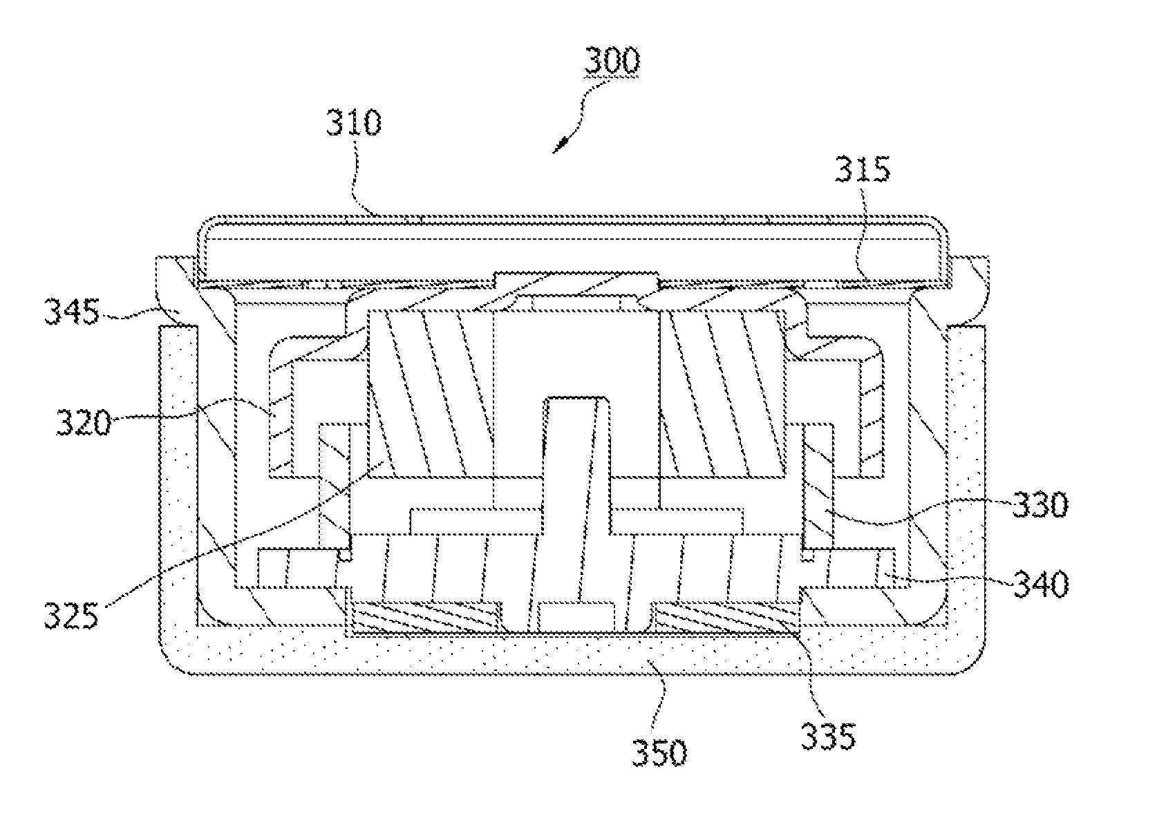
[0045]First, as shown in FIGS. 9 and 10, a communication terminal of the present invention includes at least one bone conduction vibration receiver / speaker 300 attached to an inner liquid crystal screen 401 or a rear surface of a liquid crystal panel 402 of the communication terminal (e.g., a smart phone, a Galaxy Tab, a Galaxy Phone, a mobile phone, a PDA, an MP3, an iPhone, an iPad, and a wireless set) 400 and for converting a sound signa...


PUM


Abstract

The present invention relates to a communication terminal having a bone conduction function. To this end, the present invention provides a communication terminal having a bone conduction function equipped with a bone conduction vibration receiver / speaker (300) for converting a sound signal (electric signal) into a vibration, so as to enable sound reception from the entire front surface of the communication terminal when the communication terminal closely contacts the face, and having at least one thereof attached to the rear surface of an inner liquid crystal screen (401) or liquid crystal panel (402) of the communication terminal (example: smartphone, Galaxy Tab, Galaxy Phone, cellular phone, PDA, MP3, iPhone, iPad, walkie-talkie, et cetera) (400). Also, provided is a communication terminal having a bone conduction function, comprising a bone conduction vibration no-noise microphone (200) having at least one thereof attached to the inner top section of the communication terminal (example: smartphone, Galaxy Tab, Galaxy Phone, cellular phone, PDA, MP3, iPhone, iPad, walkie-talkie, et cetera) (400), for enabling transmission / reception of the voice of a person on the phone regardless of the surrounding noise using a bone conduction microphone function when the communication terminal closely contacts the face, and for converting minute vibrations into a sound signal (electric signal).

Description

CROSS-REFERENCE TO RELATED APPLICATION[0001]The present application is the U.S. national state application of International Application PCT / KR2011 / 005308, file Jul. 19, 2011, which international application was published on Aug. 9, 2012, as International Publication WO2012 / 105735. The international application claims the benefit of Korean Patent Application No. 10-2011-0010278, filed on Feb. 1, 2011 in the Korean Intellectual Property Office, the contents of which are incorporated herein by reference in their entireties.TECHNICAL FIELD[0002]The present invention relates to a communication terminal having a bone conduction function, and more particularly, to a communication terminal having a bone conduction function that can form an entire front surface of the terminal into a screen window by removing a receiver hole (speaker) provided at the front surface of a conventional communication terminal (e.g., a smart phone, a Galaxy Tab, a Galaxy Phone, a mobile phone, a personal digital, ...

Claims


Application Information

Patent Timeline
Patent Type & Authority Patents(United States)
IPC IPC(8): H04R25/00H04R9/02H04M1/03H04R1/02H04R11/06H04M1/02H04M1/23H04R1/00
CPCH04R9/02H04M1/03H04M1/0266H04M1/23H04R11/06H04R2499/15H04R2499/11H04R2460/13H04R2400/03H04B1/40
Inventor LEE, SANG CHUL
Owner LEE SANG CHUL
Why Eureka
Try Eureka