Selective elevator braking during emergency stop

Active Publication Date: 2016-01-05
INVENTIO AG
View PDF10 Cites 3 Cited by
  • Summary
  • Abstract
  • Description
  • Claims
  • Application Information

AI Technical Summary

Benefits of technology

[0005]An objective of the present invention is to further reduce the deceleration of an elevator car during an emergency stop so as to alleviate the problems discussed above. A further objective is to reduce wear of the brake. These objectives are achieved by a method for controlling movement of an elevator car during an emergency stop comprising the steps of determining a load of the car, determining a travel direction of the car, monitoring a speed of the car and when the car is travelling downwards and is light

Problems solved by technology

Due to this increase in relative coefficient of friction, when the brake is applied in an emergency stop for an elevator employing synthetic traction mean

Method used


Image

  • Selective elevator braking during emergency stop
  • Selective elevator braking during emergency stop
  • Selective elevator braking during emergency stop

Examples


Embodiment Construction

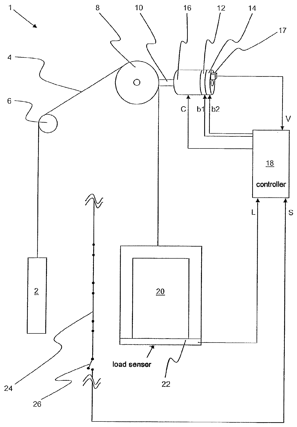
[0017]An elevator installation 1 according to the invention is shown in FIG. 1. The installation 1 is generally defined by a hoistway bound by walls within a building wherein a counterweight 2 and car 20 are movable in opposing directions along guide rails. Suitable traction means 4 supports and interconnects the counterweight 2 and the car 20. In the present embodiment the weight of the counterweight 2 is equal to the weight of the car 20 plus 40% of the rated load which can be accommodated within the car 20. The traction means 4 is fastened to the counterweight 2 at one end, passed over a deflecting pulley 6 positioned in the upper region of the hoistway, passed through a traction sheave 8 also located in the upper region of the hoistway, and fastened to the elevator car 20. Naturally, the skilled person will easily appreciate other roping arrangements are equally possible. The traction sheave 8 is driven via a drive shaft 10 by a motor 16 and braked by an electro-mechanical brake...


PUM


Abstract

A method for controlling movement of an elevator car during an emergency stop includes the steps of determining the load of the car; determining the travel direction of the car; and monitoring the speed of the car. When the car is determined to be either lightly loaded and travelling downwards, or heavily loaded and travelling upwards, brake torque is applied only when the speed of the car reaches zero, as slowing of the car can be accomplished solely by virtue of the balancing factor of the car's counterweight.

Description

BACKGROUND OF THE INVENTION[0001]In an elevator installation, an elevator car and a counterweight are conventionally supported on and interconnected by traction means. The traction means is driven through engagement with a motor-driven traction sheave to move the car and counterweight in opposing directions along the elevator hoistway. The drive unit, consisting of the motor, an associated brake and the traction sheave, is normally located in the upper end of the elevator hoistway or alternatively in a machine room directly above the hoistway.[0002]Safety of the elevator is monitored and governed by means of a safety circuit or chain containing numerous contacts or sensors. Such a system is disclosed in U.S. Pat. No. 7,353,916. Should one of the safety contacts open or one of the safety sensors indicate an unsafe condition during normal operation of the elevator, the controller instructs the drive to perform an emergency stop by immediately de-energizing the motor and applying the b...

Claims


Application Information

Patent Timeline
IPC IPC(8): B66B1/32
CPCB66B1/32
Inventor MARTINELLI, ROGERSTALDER, ROBERT
Owner INVENTIO AG
Why Eureka
Try Eureka