Optical fiber connector component and optical fiber connector provided with optical fiber connector component

a technology of optical fiber connector and optical fiber connector, which is applied in the direction of optics, fibre mechanical structures, instruments, etc., can solve the problems of poor operating efficiency disconnection of optical fiber or breakage of optical fiber connector, etc., and achieves the effect of reducing the number of optical fibers

Active Publication Date: 2016-01-05
NAMIKI PRECISION JEWEL CO LTD
View PDF12 Cites 14 Cited by
  • Summary
  • Abstract
  • Description
  • Claims
  • Application Information

AI Technical Summary

Benefits of technology

[0039]In the optical fiber connector component according to the present invention, since the ferrule, the stop ring, and the biasing means constituting the optical fiber connector component are formed to be smaller than outer dimensions of the housing and the cover member, and the optical fiber is inserted into a pipe by attaching the ferrule, the stop ring, and the biasing means to the optical fiber, the optical fiber connector component can be inserted into a thin pipe efficiently.
[0040]Also, in the optical fiber connector component according to the present invention, since the biasing means and the stop ring are formed to be equal to or smaller than the outer diameter of the flange portion formed in the ferrule holding member, getting stuck of the optical fiber connector component in the pipe can be reduced further when the optical fiber is inserted into the pipe, which enables the optical fiber to be inserted more efficiently.
[0041]Further, in the optical fiber connector component according to the present invention, since the cap formed in a tapered shape in which the outer diameter is gradually thinned toward the tip end is attached, getting stuck of the optical fiber connector component in the pipe can be reduced still further when the optical fiber is inserted into the pipe, which enables the optical fiber to be inserted still more efficiently.
[0042]In addition, since the optical fiber connector component according to the present invention includes the boot on the base end side of the stop ring, getting stuck of the optical fiber connector component in the pipe on a base end side of the optical fiber connector component can be reduced further. Accordingly, the optical fiber connector component according to the present invention enables the optical fiber to be inserted more efficiently.
[0043]Also, in the optical fiber connector component according to the present invention, the flange is formed in the stop ring, which facilitates reception of force by gas supplied in the pipe and enables the optical fiber to be inserted efficiently.
[0044]Also, in the optical fiber connector according to the present invention, since the housing and the cover member are coupled and fixed, the optical fiber connector component is arranged and fixed in the inside of the coupled body of the housing and the cover member, and the cover member and the stop ring are coupled and fixed by the fixing member, the cover member and the housing can be attached to the optical fiber connector component after the optical fiber connector component is inserted into the pipe and is pulled out of an opposed end portion. Accordingly, in the optical fiber connector according to the present invention, the optical fiber can be laid easily with use of a thin pipe, and efficient laying of the optical fiber can be achieved.

Problems solved by technology

However, the optical fiber connector has a complicated structure provided with various members such as a latch to be used when the connector is connected to an adapter and when connection to the adapter is cancelled and easily gets stuck when the optical fiber is inserted into the pipe, which may cause disconnection of the optical fiber or breakage of the optical fiber connector.
Also, when the disconnection of the optical fiber or the breakage of the optical fiber connector occurs, the optical fiber that has been inserted into the pipe has to be pulled, a new optical fiber has to be connected, or the optical fiber connector has to be replaced, and thereafter the optical fiber has to be inserted into the pipe again, which brings about poor operating efficiencies.
Especially in a case where the pipe is provided in this manner, the optical fiber connector easily gets stuck, which easily causes the aforementioned disconnection of the optical fiber or breakage of the optical fiber connector.

Method used


Image

  • Optical fiber connector component and optical fiber connector provided with optical fiber connector component
  • Optical fiber connector component and optical fiber connector provided with optical fiber connector component
  • Optical fiber connector component and optical fiber connector provided with optical fiber connector component

Examples


example 1

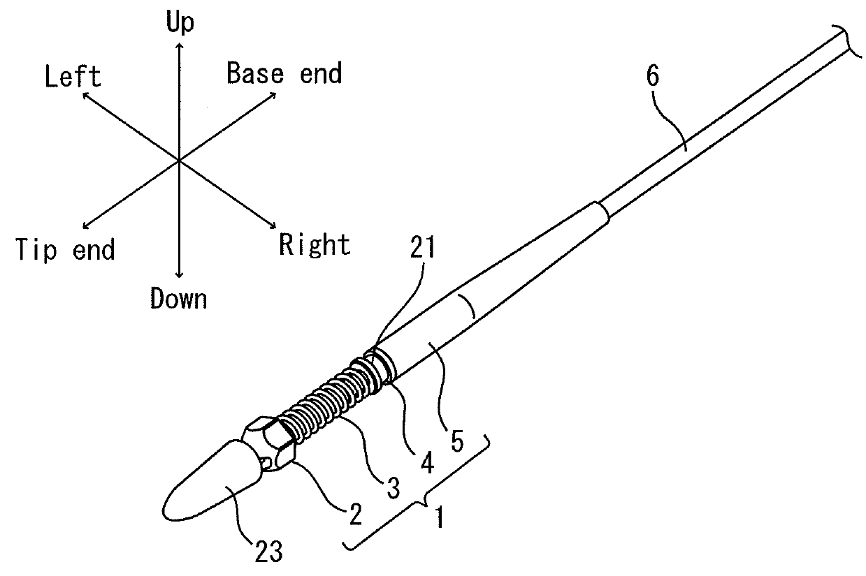
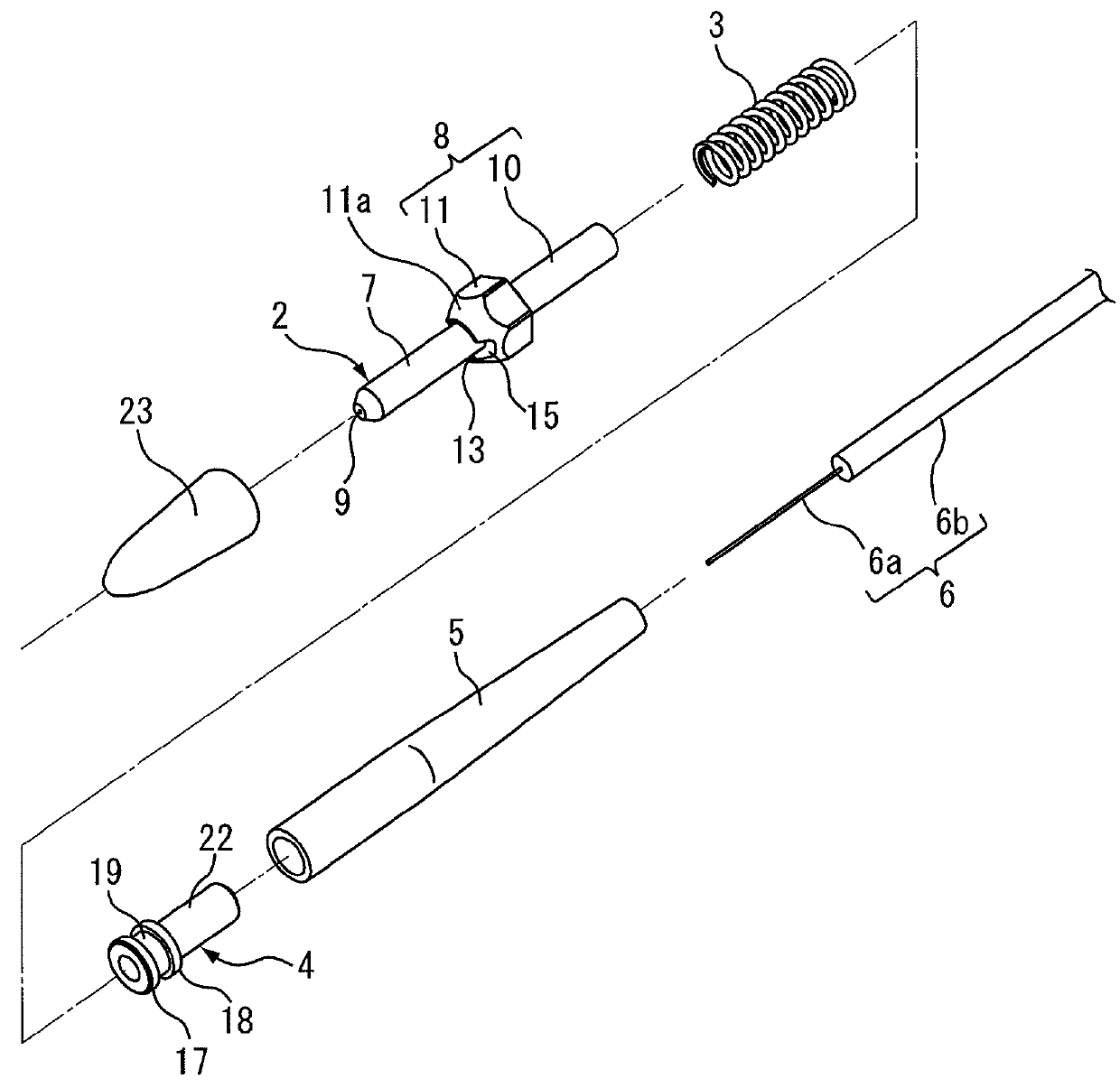
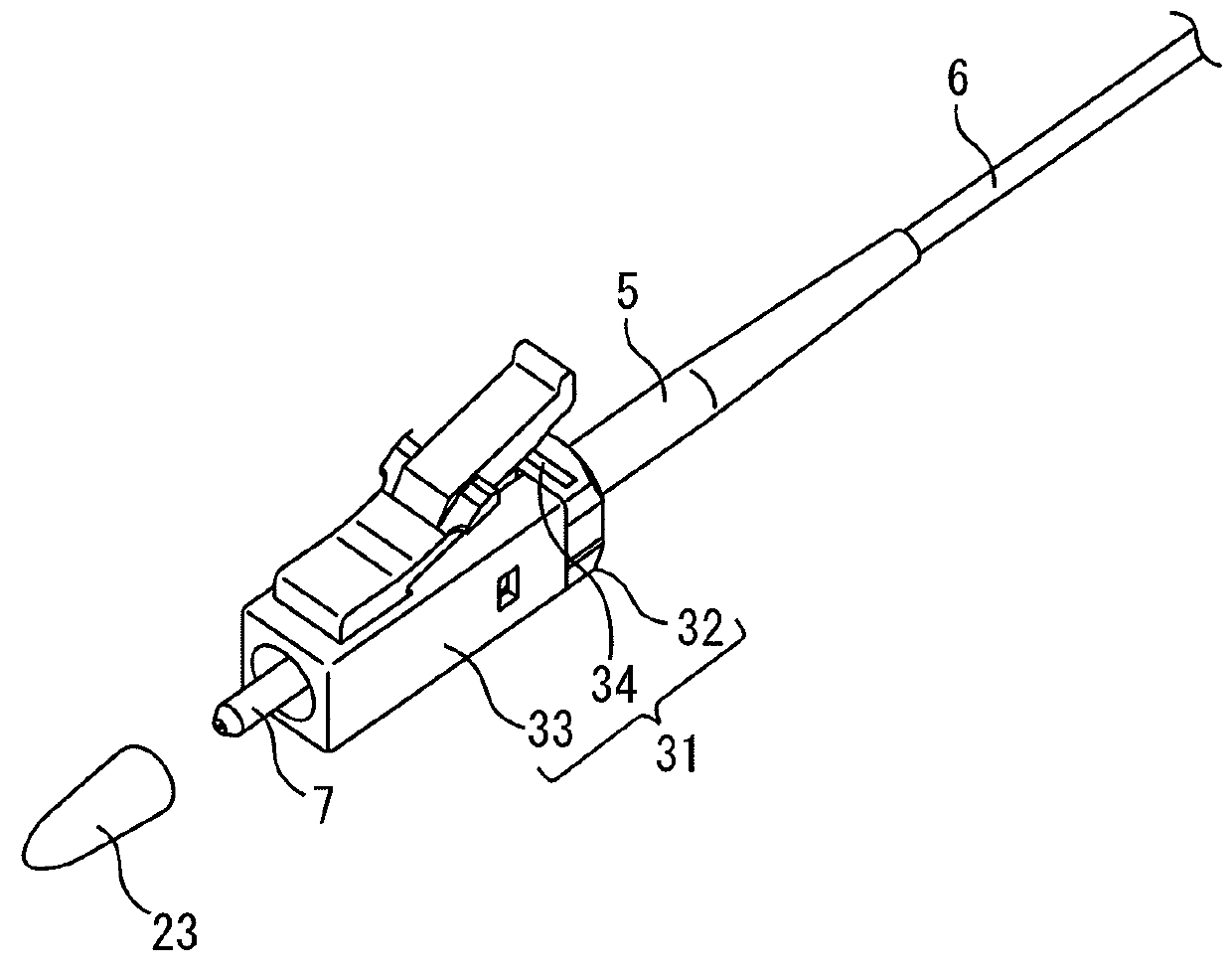
[0093]Attachment of Optical Fiber Connector Component:

[0094]In the present example, the optical fiber having a diameter of 0.9 mm and a length of 200 m was prepared. Subsequently, the boot 5, the stop ring 4, and the coil spring 3 were inserted into a tip end of the optical fiber 6, and after insertion, the cover at a tip end portion of the optical fiber 6 was removed to expose the fiber core wire 6a. The tip end portion of the optical fiber 6 was inserted and held into the ferrule 2, and the cap 23 was attached to a tip end of the ferrule main body 7. Meanwhile, in Example 1, one provided at a tip end with the flange was used as the stop ring 4, and one not subjected to a special process on a surface of the covering material was used as the optical fiber 6.

[0095](Carriage Test)

[0096]Subsequently, a feeder adapted to send the optical fiber 6 was prepared, and the optical fiber 6 attaching the optical fiber connector component 1 at a tip end was set in the feeder. Subsequently, a pip...

example 2

[0097]In Example 2, the optical fiber connector component 1 was attached to the optical fiber 6 in a similar manner to Example 1 except for not using the boot 5. Subsequently, the carriage test was performed under similar conditions to those in Example 1. A result of the carriage test in Example 2 is shown in Table 1.


PUM


Abstract

Provided are an optical fiber connector component which holds an optical fiber and is capable of being inserted through a thin pipe and capable of being inserted smoothly through a pipe, and an optical fiber connector provided with the optical fiber connector component. The optical fiber connector component comprises a ferrule having a fiber hole to hold an inserted coaxially disposed optical fiber, a stop ring arranged on the base end side of the ferrule, and an urging means arranged in between the ferrule and the stop ring; the optical fiber connector is characterized by having a housing and cover member coaxially connected to the optical fiber, and the cover member being fixed to the stop ring of the optical fiber component by means of a fixing member.

Description

TECHNICAL FIELD[0001]The present invention relates to an optical fiber connector component and an optical fiber connector provided with the optical fiber connector component.BACKGROUND ART[0002]An optical communication technique in which an electric signal is converted into an optical signal to transmit information is characterized by enabling to raise communication speed more and transmit larger-capacity data than an electric communication. Recently, such characteristics of the optical communication technique attract attention, and a newly constructed building is designed in advance so that an optical fiber can be laid at the time of construction in many cases while an existing building is also provided with an optical fiber in many cases.[0003]As a method for distributing an optical fiber, various wiring methods such as under-carpet wiring, exposed wiring, and concealed wiring are conventionally known. Recently, the concealed wiring is carried out in many cases from a viewpoint of...

Claims


Application Information

Patent Timeline
Patent Type & Authority Patents(United States)
IPC IPC(8): G02B6/38G02B6/36G02B6/44
CPCG02B6/3624G02B6/3821G02B6/3869G02B6/3849G02B6/3871G02B6/4466G02B6/54G02B6/38875G02B6/475G02B6/36G02B6/38
Inventor YAMAUCHI, ISAOHYAKUTAKE, YASUHIROKANO, SATOSHI
Owner NAMIKI PRECISION JEWEL CO LTD
Why Eureka
Try Eureka