Universal cable jacket removal tool

a universal cable and tool technology, applied in the field of electric cables, can solve the problems of long work, difficult and time-consuming operation of commercially available jacket removal tools, and inability to adjust the cutting blade, so as to reduce the force required, and reduce the effect of for

Active Publication Date: 2016-01-05
THE UNITED STATES OF AMERICA AS REPRESENTED BY THE SECRETARY OF THE NAVY
View PDF17 Cites 20 Cited by
  • Summary
  • Abstract
  • Description
  • Claims
  • Application Information

AI Technical Summary

Benefits of technology

[0004]In view of the foregoing, an object of the present invention is to provide an improved methodology for removing a jacket from an electrical power cable.
[0005]The present invention's cable-cutting device represents a fast, precise, and easily operated tool for removal of thick jacket material from cabling (e.g., naval shipboard cabling or utility power system cabling) across a broad range of cable diameters and jacket thicknesses.
[0010]According to conventional cable jacket removal, the cable jacket is cut spirally while the cable is held; the holding force and the cutting force operate in different directions at once, with continual repositioning of the hand tool. In contrast, the present invention's cable jacket removal tool eliminates the need for the practitioner to provide both the holding force and the cutting force.
[0011]As distinguished from conventional devices, the inventive device provides mechanical advantage to reduce the forces required to complete the task. The inventive device cuts linearly, as opposed to the spiral cutting by conventional devices. Typical inventive embodiments implement three blades for correspondingly creating three parallel incisions along the longitudinal axis of the cable jacket. Among the other features of the present invention is its utilization of a Kellum grip to provide all of the oppositional force to the cutting motion. Conventional cable removal methodology requires the operator to provide all of the opposition force to the cutting motion. Furthermore, the present invention's combination including a tensioning yoke assembly and wire-tension pulleys reduces the force required to perform the cutting action.
[0012]In addition, the present invention features adjustability of its cutting blades. According to typical inventive practice, the two oppositely angled lateral cutting blades are adjustable both horizontally and vertically. The third cutting blade is adjustable by means of adjustment of the horizontal cross-member (e.g., bar) to which the third cutting blade is attached. Each form of adjustability includes positional locking. By virtue of its multi-directional, multi-bladed adjustment capabilities, the present invention can accommodate practically any cable diameter and jacket type while affording accurate and reliable cutting results.
[0015]As typically practiced, the present invention's “universal cable jacket removal tool” attaches to the cable being worked. The present invention affords a faster, easier cutting action than conventional hand tools. A typical inventive device utilizes highly adjustable cutting arms built into an “M” fixture / support, along with a block-rectangle cross member. The inventive device anchors to the cable via a Kellum grip having a yoke ring end. On the other end of the inventive device is a second yoke ring, which is attributed with a tension cable-ratcheting take-up mechanism. According to some inventive embodiments, a second “M” fixture / support has rollers to smooth inventive operation. The cutting “M” fixture / support is situated between the two yoke rings. The movement of the ratchet yoke ring toward the Kellum yoke ring, via ratcheting action, causes the cutting of the cable jacket. Small pulleys in the Kellum yoke ring provide mechanical advantage, and the Kellum grip's opposition to the cutting force improves ease of operation.

Problems solved by technology

Generally speaking, commercially available jacket removal tools are imprecise hand tools that are difficult and time-consuming to operate.
Use of these hand tools requires significant training and on-the-job experience.
Their use requires lengthened and labor-intensive work, and this considerable amount of energy and effort yields inconsistent results.

Method used


Image

  • Universal cable jacket removal tool
  • Universal cable jacket removal tool
  • Universal cable jacket removal tool

Examples


Embodiment Construction

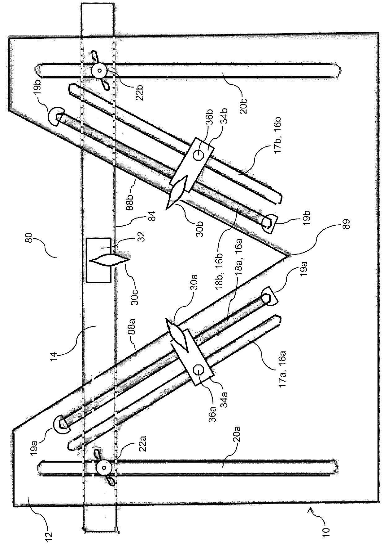
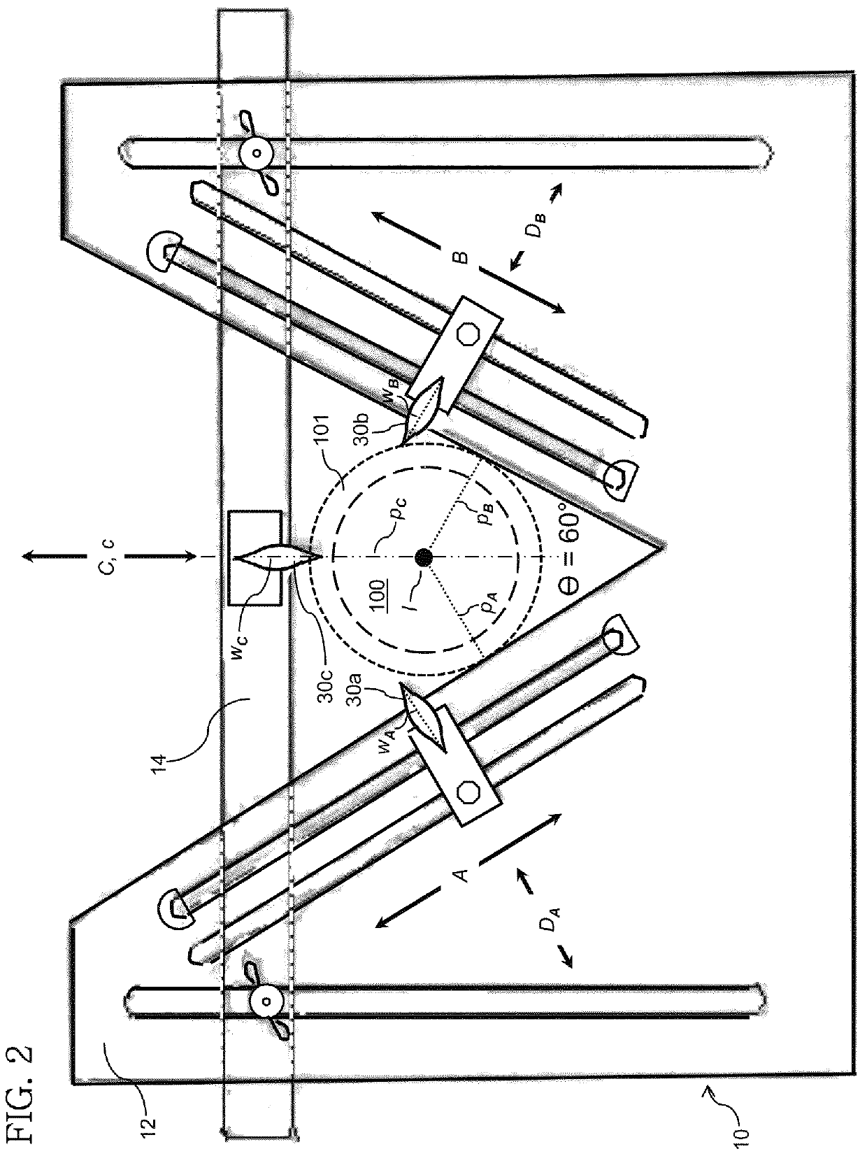
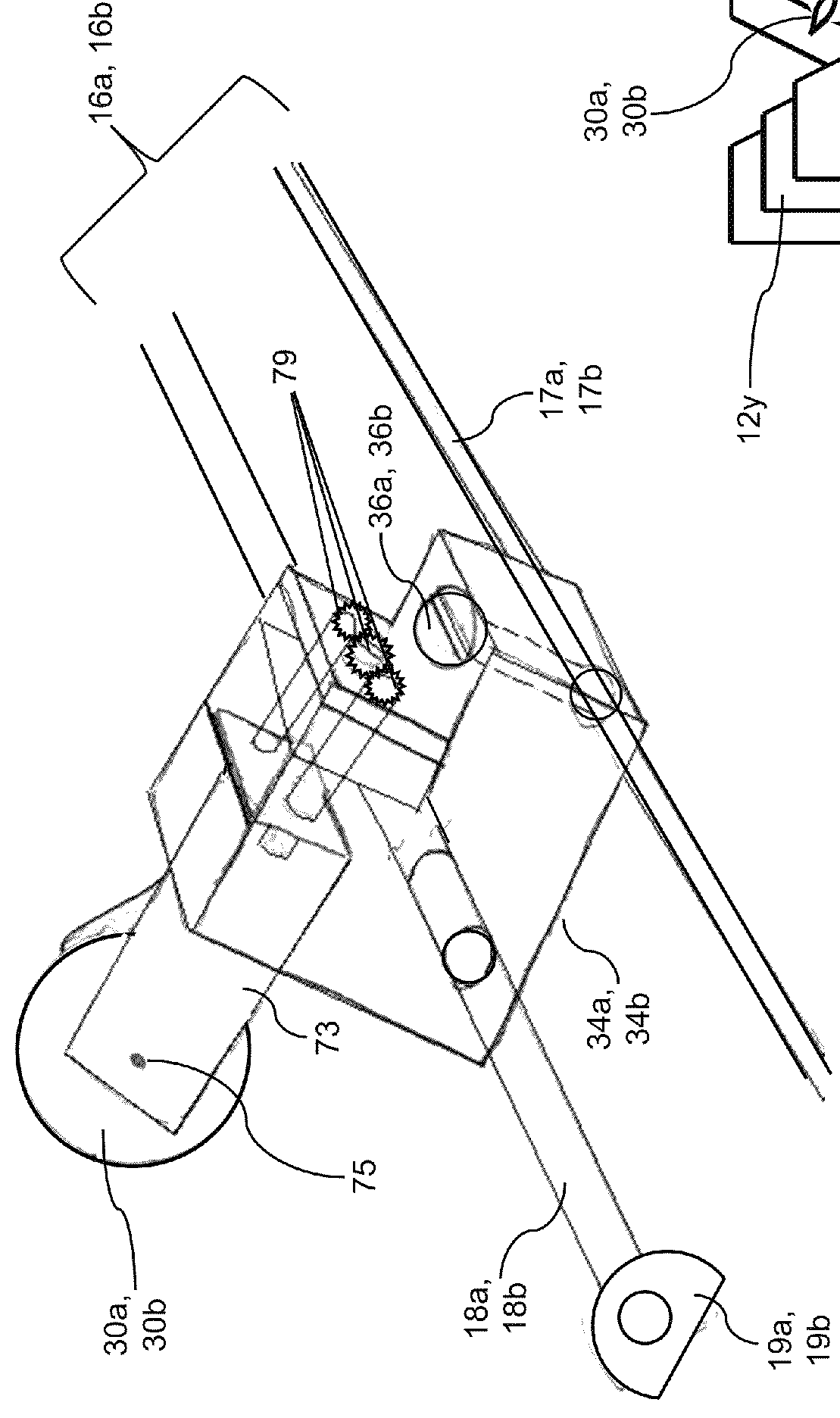
[0026]Referring now to FIG. 1 through FIG. 4, cutting assembly 10 is a mechanical unit representing the cutting component of a cable incision apparatus in accordance with typical practice of the present invention. Cutting assembly 10 includes: an “M”-shaped support plate 12; a horizontal crossbar 14; movable clips 34a and 34b; guide rails 18a and 18b; rail mounts 19a and 19b; bar lock-down nuts 22a and 22b; rotational cutting blades 30a, 30b, and 30c; blade rotational fastener 32; and, clip lock-down nuts 36a and 36b. M-shaped plate 12 is a planar support structure that is configured to have a “V”-shaped notch 80, two oblique hold-down slots 17a and 17b, and two vertical hold-down slots 20a and 20b.

[0027]Blades 30a and 30b are attached to movable clips 34a and 34b, respectively. Guide rails 18a and 18b are attached to M-shaped support plate 12 via rail mounts (e.g., including retainer clips) 19a and 19b, respectively. Guide rail 18a and hold-down slot 17a are parallel to each other...


PUM

PropertyMeasurementUnit
vertical angleaaaaaaaaaa
lengthaaaaaaaaaa
cut lengthaaaaaaaaaa

Abstract

According to typical inventive practice, a cable is grasped by a Kellum grip and is positioned through the topside “V”-notch of an “M”-structure. Two wires engage pulleys and a ratchet distanced from the pulleys. The pulleys are joined with a grip plate, attached at an axial end of the Kellum grip. The ratchet is joined with a ratchet plate, proximate and / or attached to the “M”-structure. The “M”-structure has joined therewith three blade wheels having cutting orientations in the same linear direction. The blade wheels are situated interiorly and perpendicularly in correspondence to the geometric sides of the inverted triangle defined by the “V”-notch. Each blade wheel is adjustable to suit the diameter of the cable positioned through the “V”-notch. Ratcheting of the wires moves the ratchet plate and hence the “M”-structure, resulting in creation via the blade wheels of three parallel slices in the cable along its axis.

Description

BACKGROUND OF THE INVENTION[0001]The present invention relates to electrical cables such as electrical power cables, more particularly to methods and apparatuses for removing an outer layer (e.g., a jacket or insulative layer) from an electrical cable.[0002]Generally speaking, commercially available jacket removal tools are imprecise hand tools that are difficult and time-consuming to operate. The conventional approach to removing a jacket from an electrical cable involves manipulation of a hand tool that does not attach to the cable. During the cutting of a cable, both the cable and the hand tool's cutting blades are unsupported and in free air. Use of these hand tools requires significant training and on-the-job experience. They tend to be variable both in their service life and in the quality of the electrical terminations that they permit. Their use requires lengthened and labor-intensive work, and this considerable amount of energy and effort yields inconsistent results.[0003]T...

Claims


Application Information

Patent Timeline
Patent Type & Authority Patents(United States)
IPC IPC(8): H01B15/00H02G1/12
CPCH02G1/1297H01B15/006H02G1/1217H02G1/127H02G1/126Y10S83/924Y10S83/947H02G1/1229H02G1/1239
Inventor MANNA, ERIC, D.
Owner THE UNITED STATES OF AMERICA AS REPRESENTED BY THE SECRETARY OF THE NAVY
Why Eureka
Try Eureka