Air damper

a damper and air technology, applied in the field of air dampers, can solve the problems of air dampers, air leakage between adjacent blades, and difficult sealing, and achieve the effects of reducing friction and torque, good sealing, and good sealing with the blades

Active Publication Date:
View PDF13 Cites 0 Cited by
  • Summary
  • Abstract
  • Description
  • Claims
  • Application Information

AI Technical Summary

Benefits of technology

[0020]One edge of the L-shaped side seals engages and seals to the back side of the discs and the other edge of the L-shaped side seals lap over and extends beyond the blade edges and makes a good seal with the flat sides of the blades when the blades are closed. Because of this arrangement of the discs, blades and side seals; the side seals make a good seal with the blades even when the ends of the blades are not cut square, not cut to the same lengths, and not cut so there is a tight tolerance between the blade ends and the frame of the damper.
[0021]A low friction coating is applied to the side seals to further reduce friction and the torque required to open and close the damper blades.

Problems solved by technology

Air dampers with multiple blades that rotate to modulate air flow have one common problem.
That problem is that they are difficult to make seal properly.
First, there is air leakage between adjacent blades when the blades do not fully and tightly close.
Closer tolerances and seals between blades create higher manufacturing costs and create higher friction between adjacent blades which requires more torque being applied to the blades in order to fully close them.
Also, there is air leakage between the ends of the blades and the supporting damper frame.
This leakage is due to the fact that existing side seal designs are have high leakage rates and because the lengths of the blades may not be cut precisely square, may not be cut at uniform lengths and may not be cut so that there are close tolerances between the ends of the blades and the frame.
Thus, the square configuration blade seals make it unnecessary to remove the “play” from the closure mechanism in order to fully seal between adjacent blades and makes it unnecessary to have precise parallel alignment of the blades in order for the seals to engage.
Previous air dampers may have been able to provide one or two of these advantages, but none have previously been able to provide all three of these advantages in the same unit.

Method used


Image

  • Air damper
  • Air damper
  • Air damper

Examples


Embodiment Construction

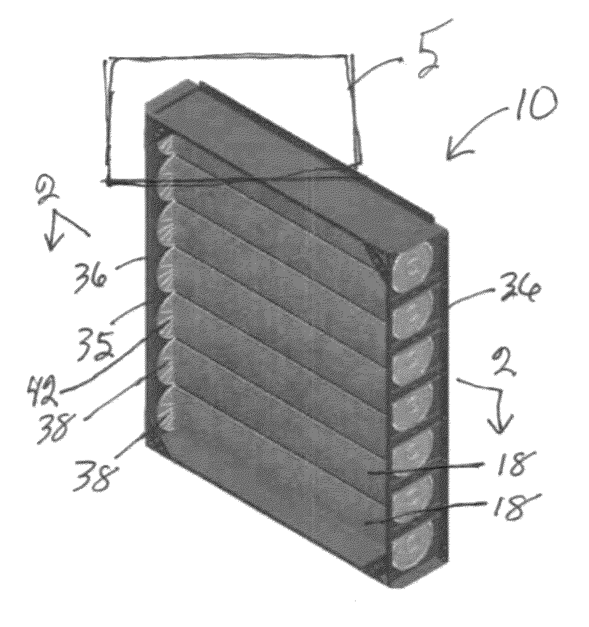
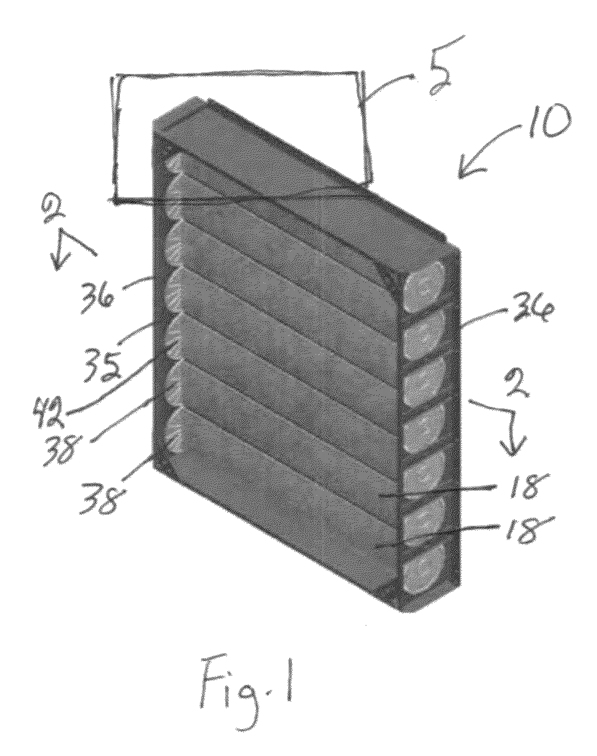
[0030]Referring now to the drawings and initially to FIG. 1, there is illustrated an air damper 10 that is constructed in accordance with a preferred embodiment of the present invention. The damper 10 is low cost to make and operate, has low torque requirements, and provides a good air seal.

[0031]Referring now to FIGS. 6 and 7, the damper 10 is provided with a blade seal 12 that is square in cross sectional configuration. The blade seal 12 is provided on one of the blade edges 14 of the damper blades 18 so that the blade seal 12 engages the opposing edge 16 of an adjacent blade 18 early, i.e. before the blades 18 are fully closed in their parallel, vertically aligned orientation. The reason the blade seal 12 engages the blade edges 16 of the adjacent blade 18 early is that a diameter “D” of the diagonal 20 of the square blade seal 12 is greater in length than the length “L” of the side 22 of the square blade seal 12. This insures a good seal between adjacent blades 18 without the ne...


PUM


Abstract

A low cost air damper that provides a good seal with low torque requirements. Blade seals of square cross sectional configuration are provided on each damper blade so that the blade seals engage adjacent blades before the blades are fully closed. L-shaped side seals and multiple discs that receive the ends of the blades serve collectively to seal between sides of the damper frame and the blades when the blades are closed even when the blades are not cut precisely. One edge of the L-shaped side seals engages and seals against the discs and the other edge of the side seals laps over and seals against a flat side of the blades and against the square blade seals. A low friction coating is applied to the side seals to further reduce friction.

Description

CROSS-REFERENCE TO RELATED APPLICATIONS[0001]The present application claims priority to Provisional Patent Application Ser. No. 61 / 529,283 for Air Damper that was filed on Aug. 31, 2011.BACKGROUND OF THE INVENTION[0002]1. Field of the Invention[0003]The present invention is an air damper that is low cost, has a low torque requirement, and makes a good seal when the blades of the air damper are closed.[0004]2. Description of the Related Art[0005]Air dampers with multiple blades that rotate to modulate air flow have one common problem. That problem is that they are difficult to make seal properly. This problem has several contributing factors.[0006]First, there is air leakage between adjacent blades when the blades do not fully and tightly close. To address this problem, closer tolerances can be introduced between adjacent blades or seals can be provided on the blades. Closer tolerances and seals between blades create higher manufacturing costs and create higher friction between adjac...

Claims


Application Information

Patent Timeline
Patent Type & Authority Patents(United States)
IPC IPC(8): F16K1/16F16K27/00
CPCF16K27/00F24F13/1406
Inventor WAKEFIELD, STEPHEN E.FLY, MARK W.
Why Eureka
Try Eureka