Eureka AIR delivers breakthrough ideas for toughest innovation challenges, trusted by R&D personnel around the world.

Optically augmented weapon locating system and methods of use

a weapon location and optical enhancement technology, applied in the field of weapon location systems, can solve the problems of limited weapon location determination, trajectories producing exaggerated errors in state vector estimates, and conventional weapon locating systems are generally inability to accurately determine the location of weapons

Active Publication Date: 2016-01-12
RAYTHEON COMMAND & CONTROL SOLUTIONS LLC
View PDF21 Cites 4 Cited by
  • Summary
  • Abstract
  • Description
  • Claims
  • Application Information

AI Technical Summary

Benefits of technology

[0006]The present invention provides to provide a system and associated method that can detect the firing location of weapons that fire projectiles with low angle trajectories.

Problems solved by technology

When the elevation angle of the bore of the fired weapon is small relative to the local earth tangent plane, conventional weapon locating systems are generally unable to accurately determine the location of the weapon.
Such low angle trajectories produce exaggerated errors in the state vector estimates.
At low angle trajectories, weapon location determination is also limited because projectile detection and tracking by radar systems can be limited by impaired lines of sight, radar multipath echoes, and clutter.
In addition, the short track life of near-in fire with low angle trajectories creates difficulties in discriminating false targets.
When the location of the firing weapon cannot be accurately determined, the ability to return precision counter fire or launch rockets at the firing weapon is impaired.

Method used

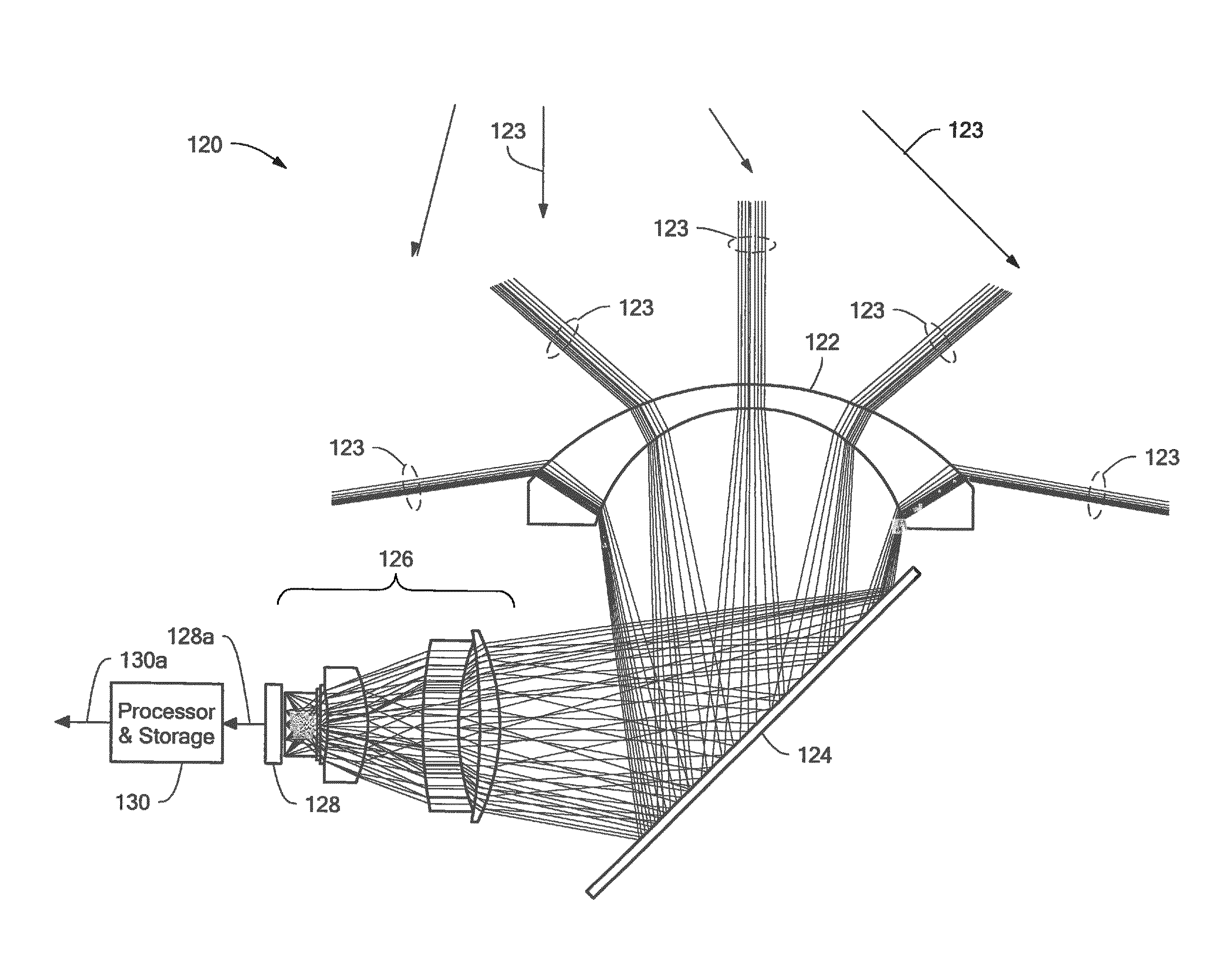
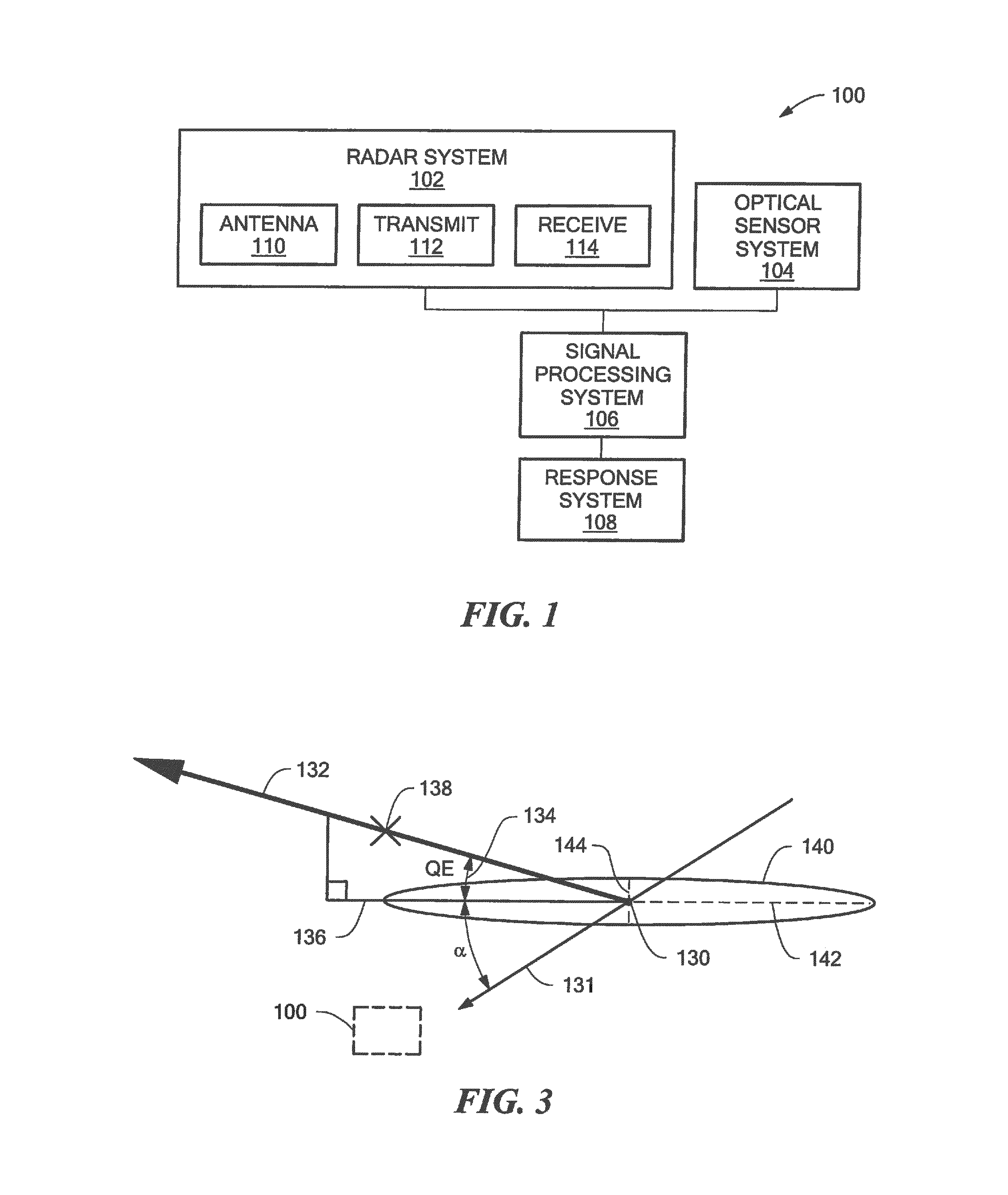
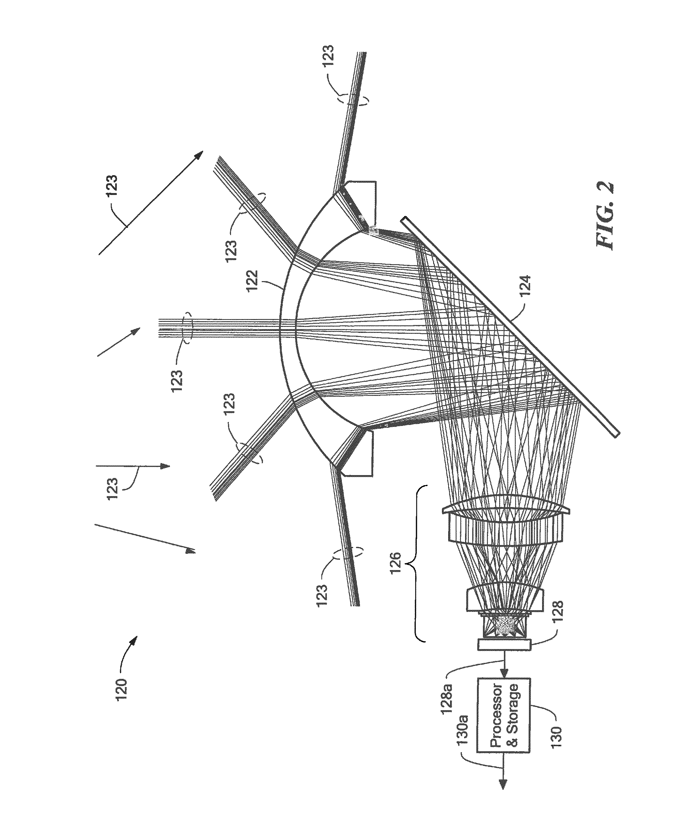

Image

  • Optically augmented weapon locating system and methods of use
  • Optically augmented weapon locating system and methods of use
  • Optically augmented weapon locating system and methods of use

Examples


Embodiment Construction

[0040]The following disclosure provides many different embodiments, or examples, for implementing different features of the invention. Specific examples of components and arrangements are described below to simplify the present disclosure. These are, of course, merely examples and are not intended to be limiting.

[0041]As used herein, the term “state vector” is used to describe a collection of parameters (i.e., one or more parameters) that correspond to set of characteristics of a moving projectile. The one or more state parameters within a state vector can include, but are not limited to, a position (in a coordinate system), a time, a speed, a heading (or three dimensional velocity vector), and acceleration in one or more dimensions, of the moving projectile.

[0042]As used herein, the term “backtracking” is used to describe a process by which one or more state vectors, each describing one or more parameters associated with a projectile at a respective one or more positions along a tr...


PUM


Abstract

A method of locating a weapon includes detecting a weapon firing event with an optical sensor, the detected weapon firing event indicative of a detected firing of the weapon and indicative of a detected time of the weapon firing event. The method also includes detecting a projectile fired from the weapon with a radar system. The method also includes calculating a state vector associated with the projectile detection. The method also includes identifying a location of the weapon by backtracking the state vector to the detected time of the weapon firing event time. The method also includes communicating the location of the weapon. A system that implements the method is also described.

Description

CROSS REFERENCE TO RELATED APPLICATIONS[0001]This application claims the benefit under 35 U.S.C. §119(e) of U.S. Provisional Application No. 61 / 510,112 filed Jul. 21, 2011, which application is incorporated herein by reference in its entirety.FIELD OF THE INVENTION[0002]This invention relates generally to weapon detection systems and, more particularly, to a weapon detection system that can identify a location of a weapon that fires a projectile with a low elevation angle.BACKGROUND OF THE INVENTION[0003]Radar systems transmit electromagnetic radiation and analyze reflected echoes of returned radiation to determine information about the presence, position, and motion of objects within a scanned area. Conventional weapon locating systems include a radar system that can detect and track projectiles, such as artillery projectiles, to determine the location of the fired weapon. This determination can be based on an extrapolation of estimated state vectors, derived by radar tracking of a...

Claims


Application Information

Patent Timeline
Patent Type & Authority Patents(United States)
IPC IPC(8): F41G3/14G01S13/86G01S13/06G01S13/72
CPCG01S13/865F41G3/147G01S13/06G01S13/723G01S13/867
Inventor RAKEMAN, JAMES, W.
Owner RAYTHEON COMMAND & CONTROL SOLUTIONS LLC
Why Eureka
Eureka Blog
Learn More