
Induction hob and method for controlling an induction hob

a technology of induction hob and induction hob, which is applied in the direction of induction heating, climate sustainability, sustainable buildings, etc., can solve the problems of inability to determine, and achieve the effect of reducing the effort for installing the pot detection sensor, allowing the production of the cooking hob, and low complexity

Active Publication Date: 2019-08-22
ELECTROLUX APPLIANCES
View PDF0 Cites 0 Cited by
  • Summary
  • Abstract
  • Description
  • Claims
  • Application Information

AI Technical Summary

Benefits of technology

This patent is about an induction hob that can detect whether a pot is placed on a heating zone and evaluate the coverage of the pot sensors to determine if it is correctly positioned. This technology allows for the merging or splitting of heating zones, and can also provide information to the user about the best energy transfer and which parts of the hob should not be exposed to the cookware. The technical effect of this patent is an improved accuracy and efficiency of the induction hob in cooking food.

Problems solved by technology

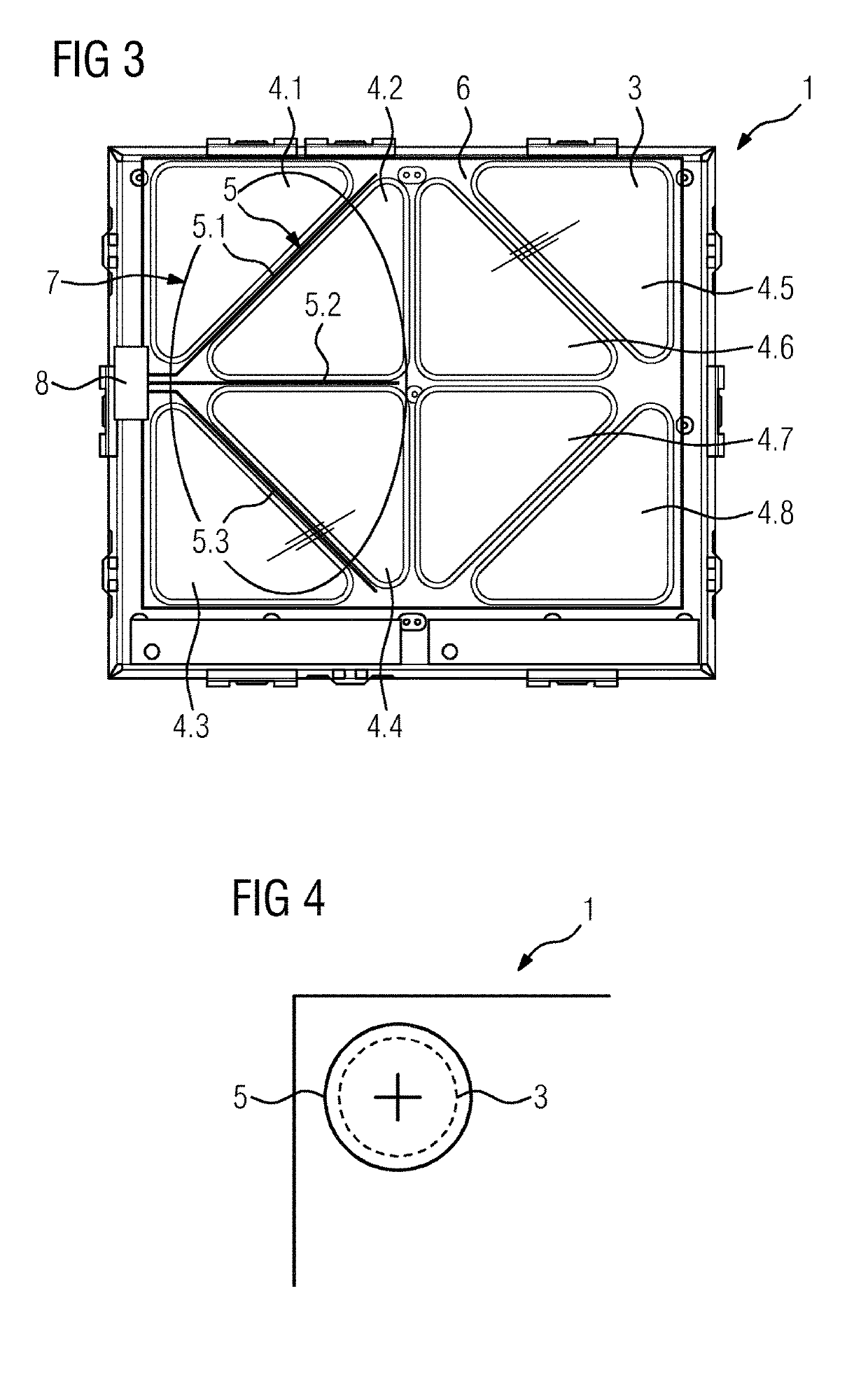
However, by using information of the induction coils it is, for example, not possible to determine whether two small-size pieces of cookware are placed on a pair of induction coils or a large-sized piece of cookware covers said pair of induction coils.

Method used


Image

  • Induction hob and method for controlling an induction hob
  • Induction hob and method for controlling an induction hob
  • Induction hob and method for controlling an induction hob

Examples


first embodiment

[0059]FIG. 6 shows an internal structure of the induction coil 3 of the example arrangement of FIG. 2.

[0060]The induction coil 3 is triangular and includes one right angle and two acute angles. In this embodiment, the induction coil 3 includes three coils 9, wherein each coil 9 is arranged within one angle of said induction coil 3. In this embodiment, the three coils 9 are circular, have the same sizes and are constructed in the same way. The use of only one type of coils 9 allows the production of the induction coil 3 by low complexity. In general, the induction coil 3 includes three or more coils 9. Preferably, the triangular induction coil 3 includes three, six or ten coils 9, if said coils have the same sizes and are equally distributed within said triangular induction coil 3.

second embodiment

[0061]FIG. 7 shows the internal structure of the induction coil 3 of the example arrangement of FIG. 2.

[0062]The induction coil 3 of the second embodiment also is triangular and includes one right angle and two acute angles. The induction coil 3 includes three coils 9, wherein each coil 9 is arranged within one angle of said induction coil 3 in each case. In this embodiment, one of the three coils 9 is circular, while the other two coils 9 are triangular. The both triangular coils 9 have the same sizes and are constructed in the same way. The circular coil 9 is arranged within the right angle of the induction coil 3, while the triangular coils 9 are arranged within the acute angles of said induction coil 3.

[0063]FIG. 8 shows the example arrangement of FIG. 2, wherein the inductions coils 3 have the internal structure according to the first embodiment.

[0064]The induction coils 3 are spatially distributed over the induction hob base area. The induction coils 3 may be arranged at the c...


PUM


Abstract

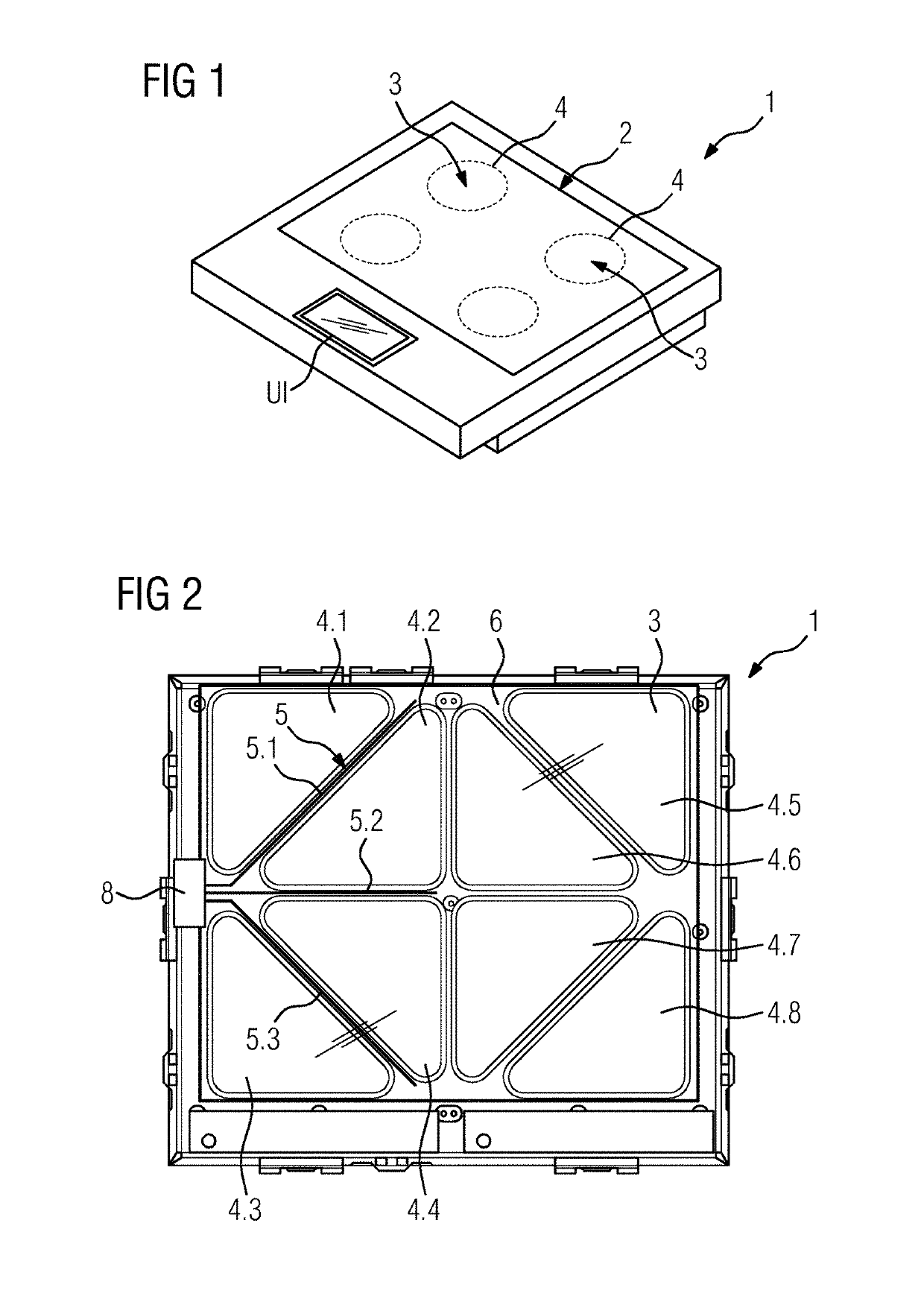
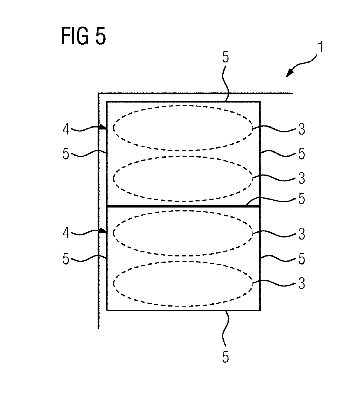
The invention relates to an induction hob comprising: a hob plate (2); two or more induction coils (3) arranged below the hob plate in order to form heating zones (4) at the hob plate (2); one or more pot detection sensors (5), the pot detection sensors (5) being at least partially placed between a pair of adjacent induction coils (3); wherein the pot detection sensor (5) is a strip-shaped sensor extending in a space between said pair of adjacent induction coils (3) and the pot detection sensor (5) is coupled with an evaluation unit adapted to determine information regarding the coverage of the pot detection sensor (5).

Description

[0001]The present invention relates generally to the field of induction hobs. More specifically, the present invention is related to an induction hob including pot detection sensors for determining the position and / or size of a piece of cookware.BACKGROUND OF THE INVENTION[0002]Induction hobs for preparing food are well known in the prior art. Induction hobs typically comprise at least one heating zone which is associated with at least one induction coil. For heating a piece of cookware placed on the heating zone, the induction coil is coupled with electronic driving means, in the following referred to as power unit, for driving an AC current through the induction coil.[0003]Induction hobs are known which comprise multiple heating zones, each heating zone being associated with one or more induction coils. In order to be able to heat large-sized pieces of cookware, two or more heating zones can be merged in order to form a heating zone area according to the base area of the piece of ...

Claims


Application Information

Patent Timeline
Patent Type & Authority Applications(United States)
IPC IPC(8): H05B6/06H05B6/12
CPCH05B6/065H05B6/1272H05B2213/05H05B6/062Y02B40/00
Inventor HOFFMANN, HARALDHOLZINGER, JOCHENKLEIN, GERHARD
Owner ELECTROLUX APPLIANCES
Learn More