Dimmable LED lighting circuits, controllers therefor and a method of controlling a dimmable LED lighting circuit

a led lighting circuit and dimmable technology, applied in lighting devices, light sources, electrical appliances, etc., can solve the problems of complicated switching led drivers, incompatibility with standard switching led drivers, and unsatisfactory solutions, and achieve the effect of reducing the overall cost of the circuit and being easy to implemen

Inactive Publication Date: 2016-01-12
NXP BV
View PDF11 Cites 0 Cited by
  • Summary
  • Abstract
  • Description
  • Claims
  • Application Information

AI Technical Summary

Benefits of technology

[0012]Thus embodiments may provide a low-cost solution which may be simple to implement and may be compatible with a standard off-the-shelf LED driver.
[0013]In embodiments the bypass circuit comprises a controllable current source. In embodiments, the bypass circuit comprises a transistor configured to be operated in a linear mode. The amount of current through the bypass circuit may thus be adjusted by controlling the control terminal of the transistor. In other embodiments, the bypass circuit comprises a pair of transistors connected as an output stage, and configured to operate in linear mode. Use of a pair of transistors may reduce the overall cost of the circuit.
[0015]In embodiments, either the controller or the bypass circuit is configured to supply the first part from a power source having a higher voltage than a power source which supplies the second part. Thereby, the voltage drop across the bypass circuit may be made to be less than the voltage drop across the at least one LED of the second type. Thus Ohmic losses associated with the bypass circuit may be reduced or minimised. In other embodiments, either the controller or the bypass circuit is configured to supply the first and second parts from a single power source.
[0021]In embodiments, the first type is an amber LED and the second type is a white LED. By generally increasing the relative contribution of the LEDs of the second type, which may typically correspond to a higher colour temperature, the perceived colour temperature of the arrangements may be increased with increasing brightness. It will be appreciated, that in less typical embodiments it may that the LEDs of the first type have a higher colour temperature, in which case, increasing brightness might generally result in a perceived lower colour temperature.

Problems solved by technology

It will be apparent, that this is not an ideal solution, from a cost point of view, since the cost-efficiency of such a system, in lumens-per-dollar, is lower than would be the case, were the amber LED also to be contributing.
However, this results in a complicated switching LED driver which may also be specific to a particular arrangement of LED strings and thus incompatible with standard switching LED drivers.

Method used


Image

  • Dimmable LED lighting circuits, controllers therefor and a method of controlling a dimmable LED lighting circuit
  • Dimmable LED lighting circuits, controllers therefor and a method of controlling a dimmable LED lighting circuit
  • Dimmable LED lighting circuits, controllers therefor and a method of controlling a dimmable LED lighting circuit

Examples


Embodiment Construction

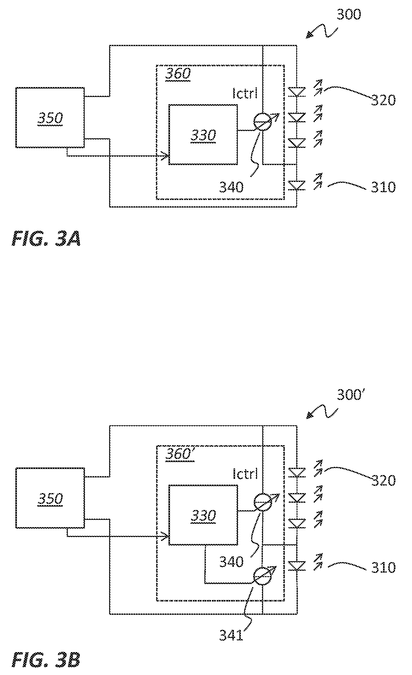
[0036]FIG. 3A shows, schematically, an LED lighting arrangement 300 according to embodiments, with two strings arranged in series; the arrangement comprises a first string of at least one LED of a first type 310 connected in series with a second string of at least one LED of a second type 320. As shown, the first string may be a single LED. It may be an amber LED. The second string may be a string of for example 3 LEDs as shown, which may be white LEDs. The arrangement 300 includes a control circuit 330 and a bypass circuit 340. The bypass circuit 340 may be a variable current sink, and is for sinking (or sourcing) a controllable current IB. A driver 350, which may be comprised in the arrangement 300, supplies an LED drive current Idriver. The LED drive current Idriver is split into two parts. The first part IW is directed through the second string 320, and the second part IB is directed through the bypass circuit. Thus all of the drive current is directed through the first string 3...


PUM


Abstract

Controllers (360, 360′), lighting circuits and methods are disclosed, for a dimmable LED lighting circuit having a series arrangement of two types of LED, the controller comprising a control circuit (330), a bypass circuit (340) and optionally a further bypass circuit and being operable for controlling a current, the current (Idriver) being separable into first and second parts (IW, IB), and into further first and second parts, wherein the controller is configured to direct the (further) first part through the LED or LEDs of the second (first) type and direct the (further) second part through the (further) bypass circuit (respectively), and wherein the control circuit is configured to adjust the ratio between the first, or further first, part and the second, or further second respectively, part in dependence on a dimming level of the LED lighting circuit.

Description

CROSS-REFERENCE TO RELATED APPLICATIONS[0001]This application claims the priority under 35 U.S.C. §119 of European patent application no. 13194657.6, filed on Nov. 27, 2013 and European patent application no. 13164929.5 filed Apr. 23, 2013, the contents of which are incorporated by reference herein.FIELD OF THE INVENTION[0002]This invention relates to dimmable lighting circuits, to controllers therefore and to methods of controlling dimmable LED lighting circuits.BACKGROUND OF THE INVENTION[0003]LED light sources differ significantly from incandescent light sources in that they typically produce light, the colour of which does not change significantly with their brightness. This is particularly apparent when an LED light source is used to replace a dimmable incandescent lamp. Depending on the brightness of the light, incandescent lamps produce light with a colour temperature between 1800K, when the lamp is deep dimmed, and 2700K when the lamp is at full brightness or even up to 3000...

Claims


Application Information

Patent Timeline
Patent Type & Authority Patents(United States)
IPC IPC(8): H05B33/08H05B44/00
CPCH05B33/0845H05B33/083H05B33/0857H05B45/385H05B45/3577H05B45/20H05B45/48
Inventor VAN, DEN, BROEKE, LEENDERT
Owner NXP BV
Why Eureka
Try Eureka