Driving force transmission control apparatus

a technology of transmission control and driving force, which is applied in the direction of mechanical actuated clutches, transportation and packaging, mechanical equipment, etc., can solve the problem that the multi-disc clutch cannot be pressed before the four-wheel drive vehicle is started, and achieve the effect of enhancing the accuracy of the driving force transmitted through the multiple-disc clutch

Active Publication Date: 2016-01-26
JTEKT CORP
View PDF23 Cites 3 Cited by
  • Summary
  • Abstract
  • Description
  • Claims
  • Application Information

AI Technical Summary

Benefits of technology

[0011]An object of the present invention is to provide a driving force transmission control apparatus in which the accuracy of a driving force transmitted through a multiple disc clutch can be enhanced.

Problems solved by technology

However, in this driving force transmission device, the cam mechanism is operated due to relative rotation between the outer housing and the inner shall, and accordingly, the multiple disc clutch cannot be pressed before the four wheel drive vehicle is started.

Method used


Image

  • Driving force transmission control apparatus
  • Driving force transmission control apparatus
  • Driving force transmission control apparatus

Examples


first embodiment

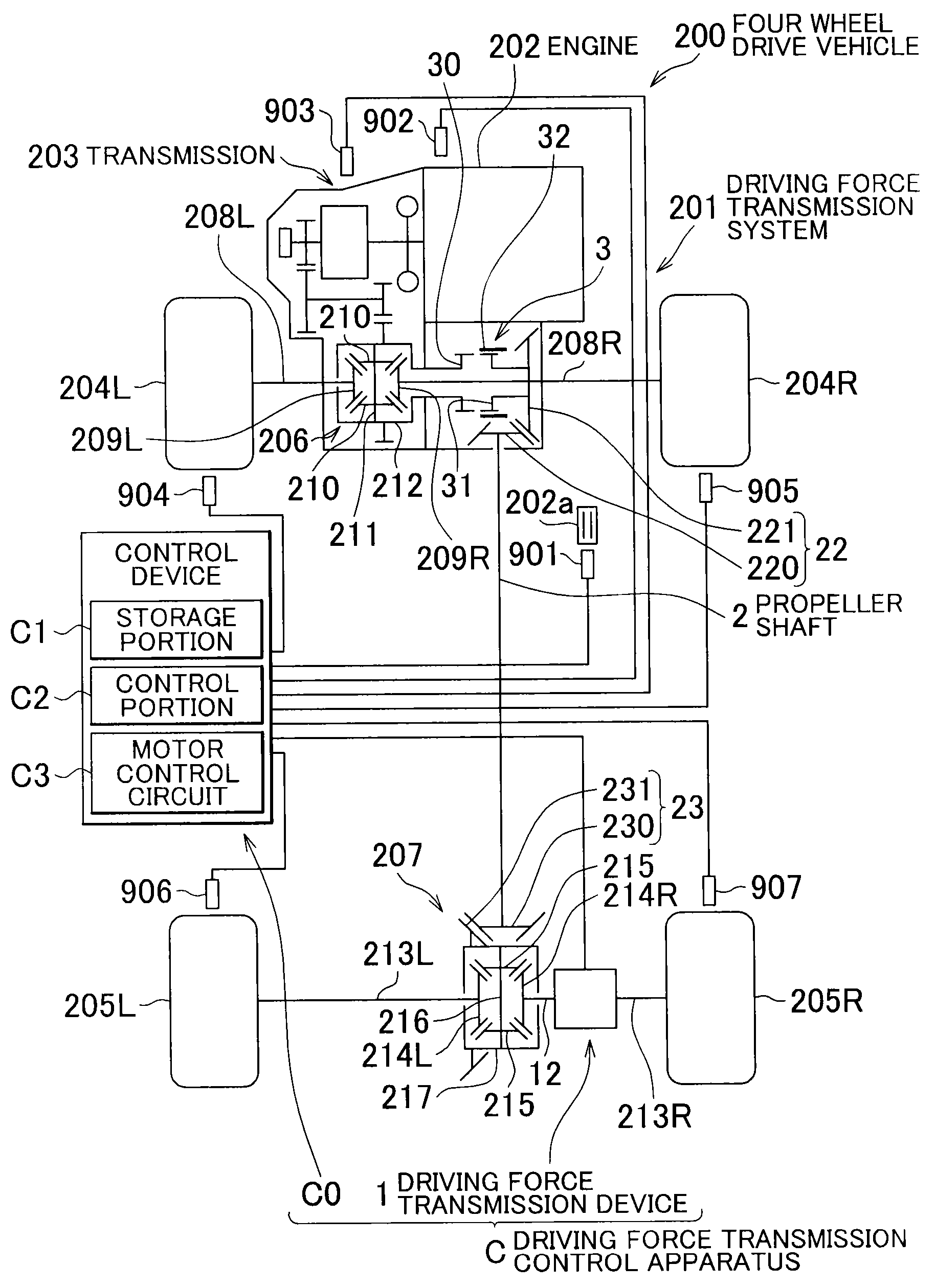
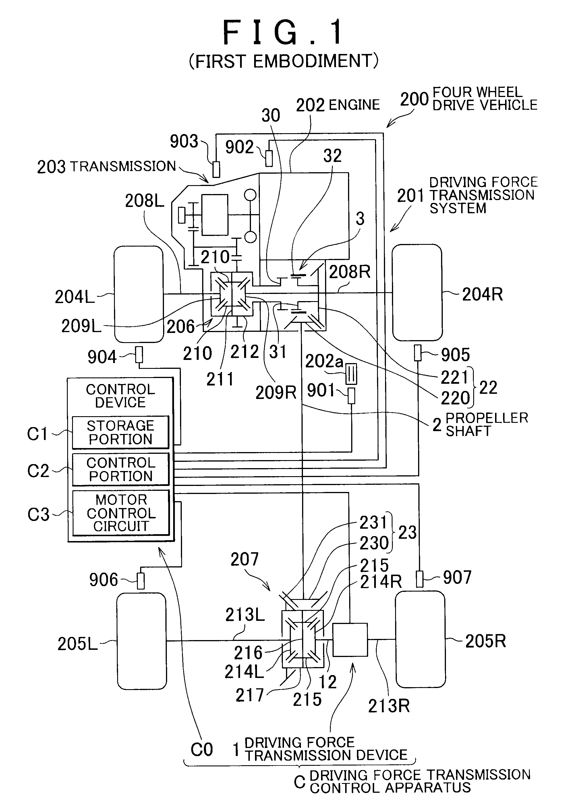
[0028]FIG. 1 is a configuration diagram showing a schematic configuration of a four wheel drive vehicle according to the present invention. The four wheel drive vehicle 200 includes a driving force transmission system 201, an engine 202 serving as a drive source, a transmission 203, front wheels 204R, 204L as main drive wheels, and rear wheels 205R, 205L as auxiliary drive wheels. The engine 202 is an example of the drive source for driving the four wheel drive vehicle 200, that is, the drive source for starting and accelerating the four wheel drive vehicle 200. However, both of an engine and an electric motor may be used as the drive source. Further, instead of the engine, an electric motor may be used as the drive source for driving the vehicle.

[0029]The driving force transmission system 201 is arranged on a driving force transmission path from the transmission 203-side to the rear wheels 205R, 205L-side in the four wheel drive vehicle 200 together with a front differential 206 an...

second embodiment

[0112]Next, the present invention will be described.

[0113]FIG. 10 is a configuration diagram showing a schematic configuration of a four wheel drive vehicle 200A according to the second embodiment. In FIG. 10, the same reference characters and numerals are assigned to the constituent elements having the functions that are substantially the same as those of the constituent elements described with reference to FIG. 1 in the first embodiment, and the duplicated descriptions thereof will be omitted.

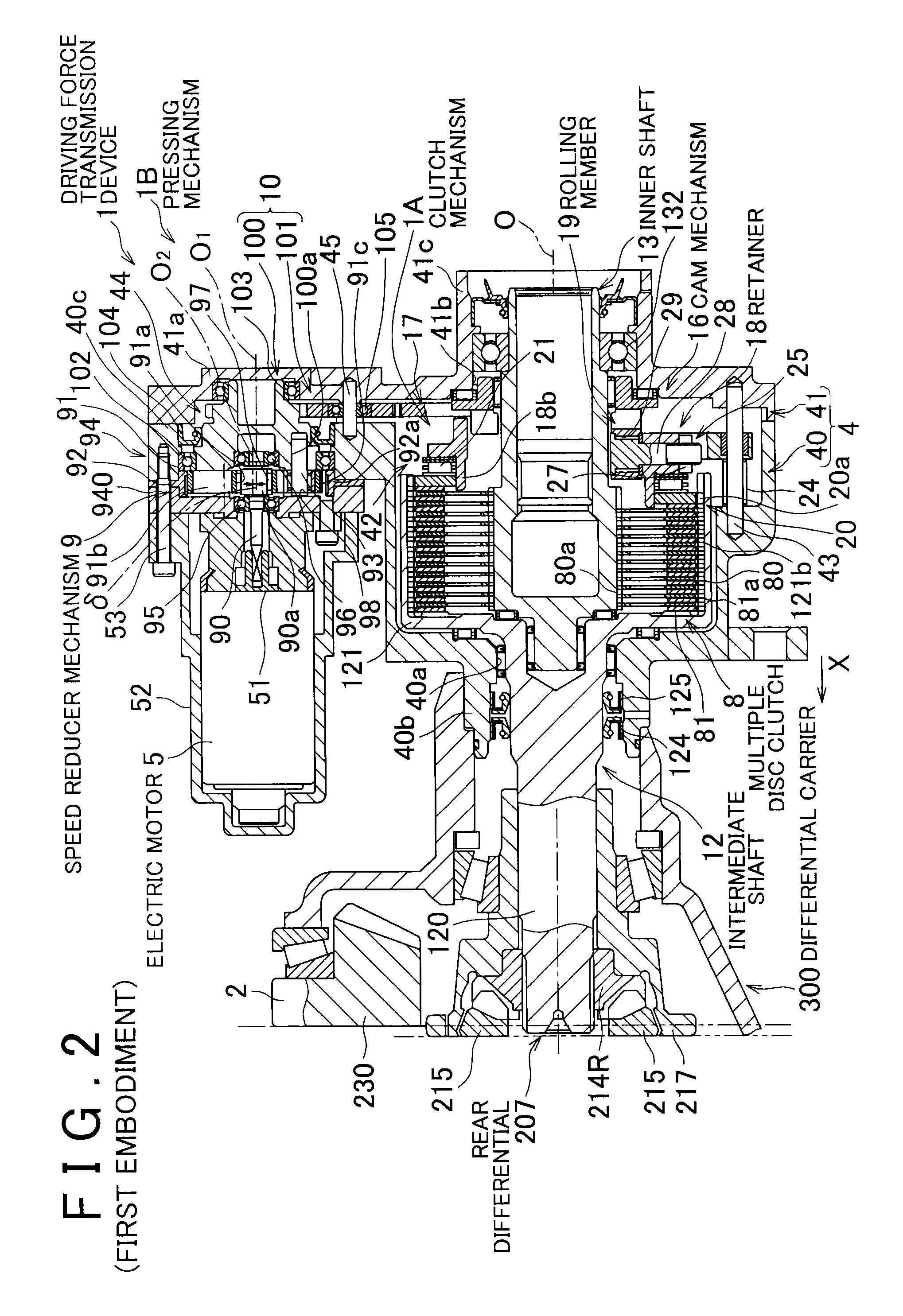
[0114]In the first embodiment, the description is provided on the case where the driving force transmission device 1 includes the clutch mechanism 1A having the multiple disc clutch 8 and the pressing mechanism 1B that applies a pressing force to the multiple disc clutch 8, and the pressing mechanism 1B is operated by the torque of the electric motor 5. However, a driving force transmission device 1000 according to the second embodiment is different from the driving force transmission device ...

third embodiment

[0144]A third communication passage 1131c is formed in the large diameter tubular portion 1311 of the casing body 1310 in addition to the first communication passage 1131a and the second communication passage 1131b. A low pressure pipe 1104 that communicates with a low pressure port of the pressure control valve 1105 is connected to the third communication passage 1131c. The pressure control valve 1105 is arranged between the hydraulic oil pipe 1102 and the low pressure pipe 1104. When the hydraulic pressure in the hydraulic oil pipe 1102 becomes equal to or higher than a predetermined value, the pressure control valve 1105 causes the hydraulic oil in the hydraulic oil pipe 1102 to flow into the drain chamber D through the low pressure pipe 1104, so as to control the hydraulic pressure in the hydraulic pressure chamber R to the above-described predetermined value. The control hydraulic pressure (the above-described predetermined value of the hydraulic pressure) of the pressure cont...


PUM


Abstract

A driving force transmission control apparatus includes a multiple disc clutch including a plurality of outer clutch plates, and a plurality of inner clutch plates; a pressing mechanism that presses the multiple disc clutch; and a control portion that controls the pressing mechanism. The outer clutch plates and inner clutch plates are engaged with an intermediate shaft and an inner shaft respectively. The control portion makes a determination as to whether the multiple disc clutch is in a first operating condition in which the multiple disc clutch is pressed with a relative rotation speed between the intermediate and the inner shafts being equal to or higher than a predetermined value, or in a second operating condition in which the multiple disc clutch is pressed with the relative rotation speed being lower than the predetermined value, and the control portion controls the pressing mechanism based on a result of the determination.

Description

INCORPORATION BY REFERENCE[0001]The disclosure of Japanese Patent Application No. 2012-267370 filed on Dec. 6, 2012 including the specification, drawings and abstract is incorporated herein by reference in its entirety.BACKGROUND OF THE INVENTION[0002]1. Field of the Invention[0003]The invention relates to a driving force transmission control apparatus that transmits a driving force in, for example, a vehicle.[0004]2. Description of Related Art[0005]There has been provided a driving force transmission system in a four wheel drive vehicle, in which a dog clutch is arranged between a propeller shaft and a drive source (engine), and a driving force transmission device capable of continuously adjusting a transmitted driving force is arranged between the propeller shaft and auxiliary drive wheels (rear wheels). Refer to, for example, Japanese Patent Application Publication No. 2012-61923 (JP 2012-61923 A).[0006]In the four wheel drive vehicle described in JP 2012-61923 A, if it is determ...

Claims


Application Information

Patent Timeline
Patent Type & Authority Patents(United States)
IPC IPC(8): F16D13/54B60K17/344F16D23/12F16D28/00B60K23/08F16D48/06F16D121/04F16D121/24
CPCF16D13/54B60K17/344B60K23/0808F16D23/12F16D28/00B60K2023/0833B60K2023/0858B60W2510/0208B60W2510/0241B60W2710/027F16D48/06F16D2023/123F16D2121/04F16D2121/24F16D48/066F16D2500/1024F16D2500/10431F16D2500/10462F16D2500/30406F16D2500/3067F16D2500/30806F16D2500/3115F16D2500/3144F16D2500/50236F16D2500/70404F16D2500/70406B60W2510/0225
Inventor KODAMA, AKIRATANIGUCHI, KENTA
Owner JTEKT CORP
Why Eureka
Try Eureka