
Method for calibrating a slope sensor

a technology of slope sensor and calibration method, which is applied in the direction of liquid/fluent solid measurement, instruments, transportation and packaging, etc., can solve the problems of aging effect of inclination sensor, and achieve the effect of increasing the rolling resistance f_roll

Inactive Publication Date: 2012-03-15
ZF FRIEDRICHSHAFEN AG
View PDF2 Cites 1 Cited by
  • Summary
  • Abstract
  • Description
  • Claims
  • Application Information

AI Technical Summary

Benefits of technology

[0021]However, to increase the accuracy of the driving resistances F_Fw1, F_Fw2 determined for the two driving directions, it can also be provided that the driving resistance F_Fw1, F_Fw2 in each respective driving direction, used for the comparison, is in each case determined as the average of an appropriate number of several successively determined driving resistance values F_Fw1, F_Fw2.
[0025]Since driving round a curve increases the rolling resistance F_Roll, for example due to abrasion of the wheel tires, it is expedient to detect the steering angle of the vehicle's steering system and / or the transverse acceleration of the motor vehicle, and to interrupt the determination of the driving resistance F_Fw1, F_Fw2 and that of a current offset value x_Offset of the inclination sensor for the duration Δt_U of a recognized drive round a curve.
[0026]Likewise, owing to road unevenness and a loose subsurface, off-road driving also increases the rolling resistance F_Roll. Accordingly, it is preferably provided that unevenness of the road and / or transverse tilting of the motor vehicle and / or the engagement of an off-road gear in the transmission are detected, and the determination of the driving resistance F_Fw1, F_Fw2 and of a current offset value x_Offset of the inclination sensor are interrupted for the duration Δt_U of recognized off-road driving.

Problems solved by technology

Furthermore, inclination sensors are subject to aging effects which can also lead to indication of an upward or downward road inclination even though the vehicle concerned is on level ground.
Whereas, when the motor vehicle is first used or first re-used, this should be possible without problems for a trained technician driving along a level test stretch, if the calibration function is manually initiated by a driver driving during normal driving operation there is a risk that a slight upward or downward road inclination will be erroneously perceived by the driver as horizontal, or that in the act of initiating and monitoring the calibration function the driver will be distracted in a safety-relevant manner from watching the traffic situation, or that initiation of the calibration function at the appropriate time will be forgotten by the driver and will therefore be omitted.

Method used


Image

  • Method for calibrating a slope sensor
  • Method for calibrating a slope sensor
  • Method for calibrating a slope sensor

Examples


Embodiment Construction

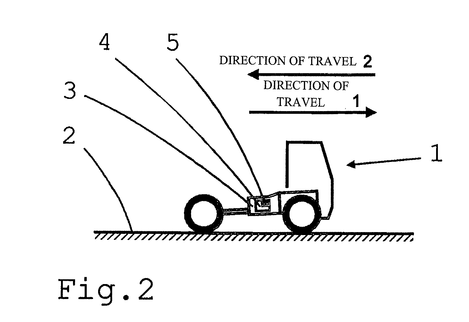
[0038]In FIG. 2 a schematically represented motor vehicle 1, in this case a truck, is on a level, i.e. horizontal road 2. The drive-train of the motor vehicle 1 contains a semi-automatic transmission 3 with a transmission control unit 4, in or on which is arranged an inclination sensor 5 for determining the road inclination α_Fb and the inclination-related resistance F_Steig.

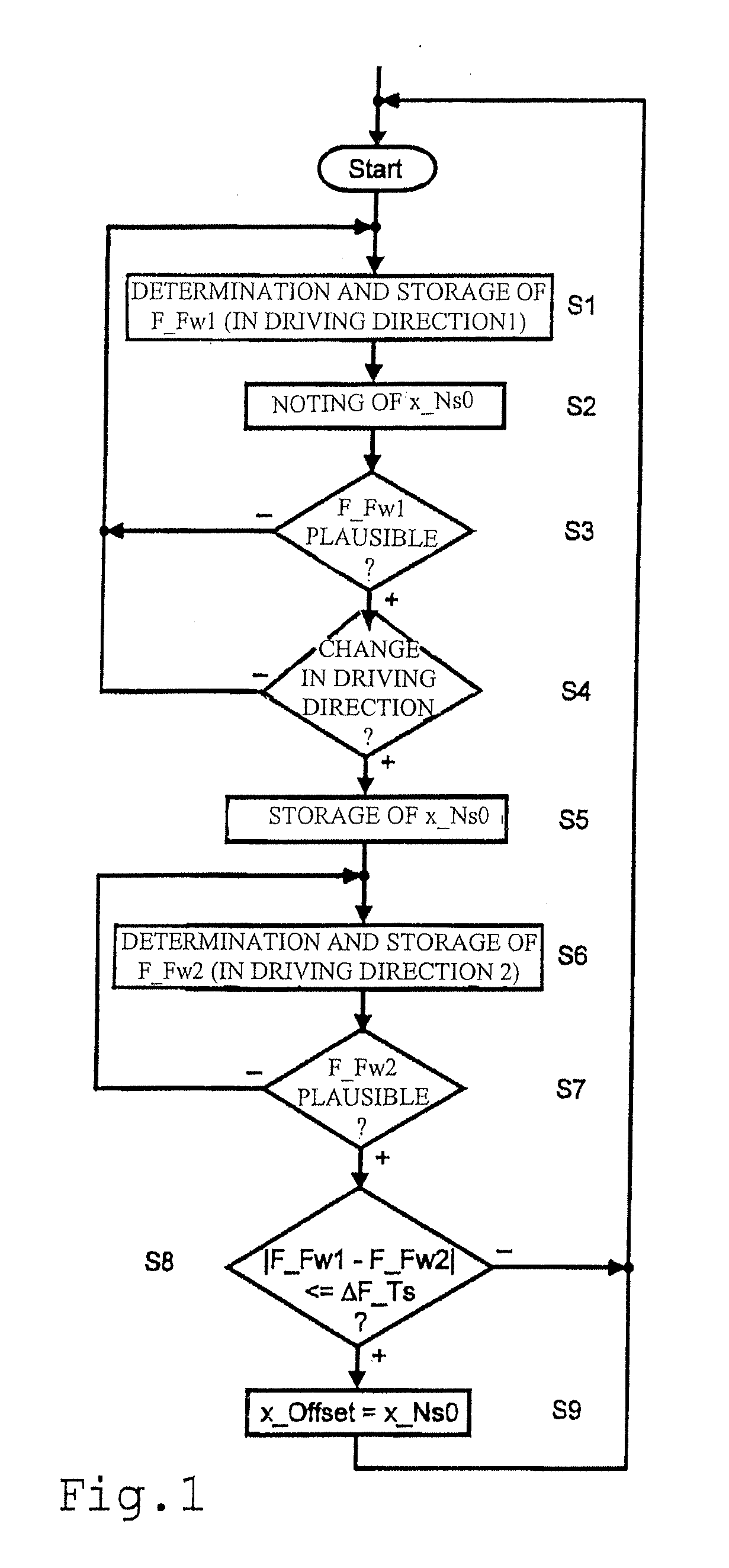
[0039]In the method described below a driving direction change, i.e. a change from driving in a first direction, for example forward, to driving in a second direction, for example reversing, is used for recognizing a level or horizontal road 2 and in such a case storing the detected raw signal value x_Ns0 of the inclination sensor 5 as the current offset value x_Offset for the zero-point correction of the inclination sensor 5.

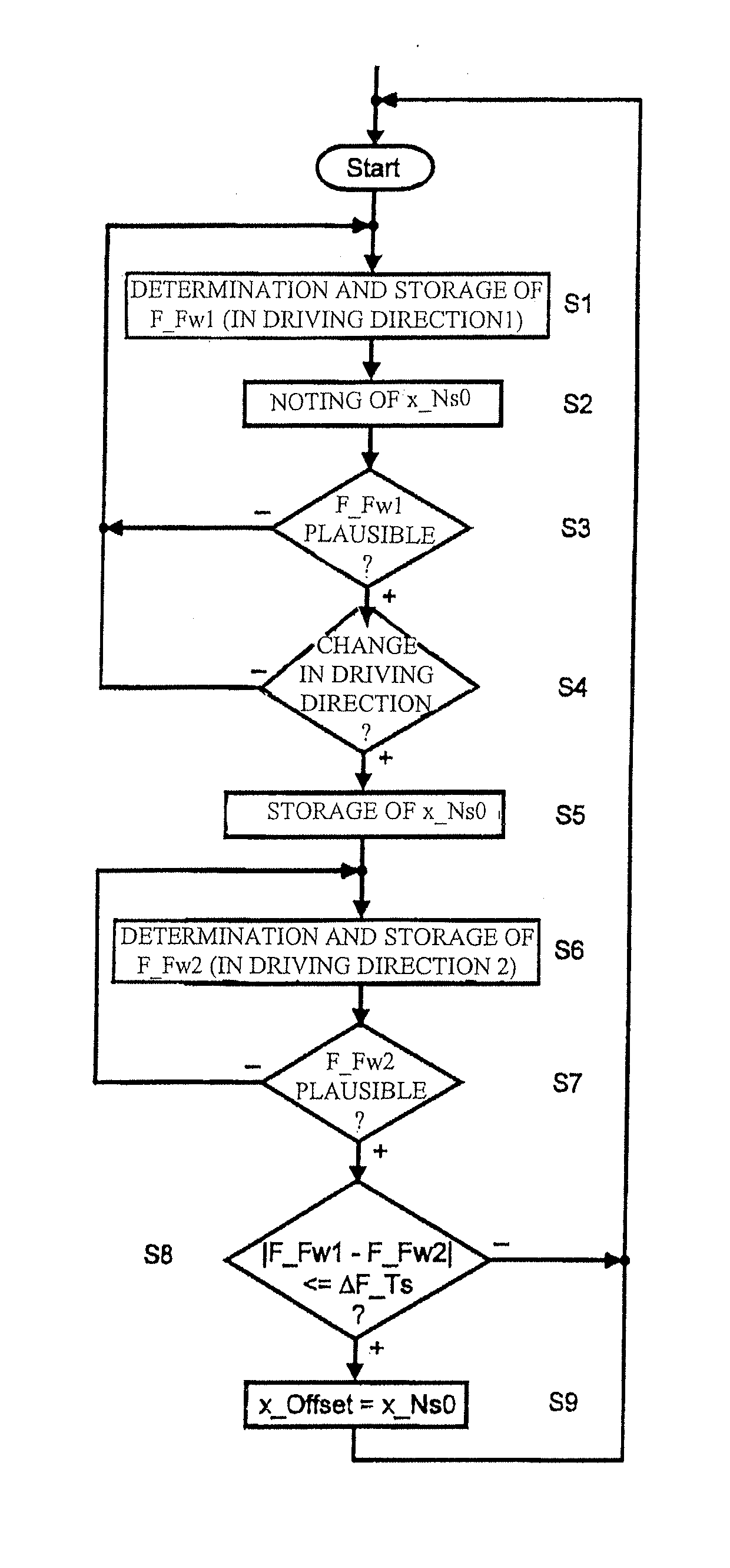
[0040]The method, represented in simplified form in the flow-chart of FIG. 1, starts when the motor vehicle 1 begins operating and drives in a first direction, for example forward. In proce...


PUM


Abstract

A method for automatically determining a current offset value for the zero-point correction of a vehicle inclination sensor including the steps of while driving in a first driving direction, the current driving resistance is determined repeatedly, without regard to the sensor and stored temporarily, and a current raw signal value of the sensor is noted. Upon a change in the driving direction, the last-noted raw signal value is stored temporarily and while driving in the second driving direction. The current driving resistance is determined repeatedly, without regard to the sensor and stored temporarily. Then, if the difference between the two stored driving resistances agree with a tolerance threshold, the noted raw signal value is stored as the offset value for the zero-point correction of the inclination sensor.

Description

[0001]This application is a National Stage completion of PCT / EP2010 / 053161 filed Mar. 12, 2010, which claims priority from German patent application serial no. 10 2009 026 688.7 filed Jun. 3, 2009.FIELD OF THE INVENTION[0002]The invention concerns a method for calibrating a slope sensor which is arranged in a motor vehicle with a semi-automatic transmission for determining the inclination of the road and the inclination-related resistance, and is connected for signal transmission purposes to the transmission control unit of the transmission.BACKGROUND OF THE INVENTION[0003]For controlling the gear ratio change processes in a semi-automatic transmission, besides the driving speed v_F of the motor vehicle, the engine rotational speed of the drive engine and the power demanded by the driver, the driving resistance F_Fw is an essential input parameter. In a moving motor vehicle in each case the shifting speed and the target speed of the next gearshift, i.e. the timing and the target gea...

Claims


Application Information

Patent Timeline
Patent Type & Authority Applications(United States)
IPC IPC(8): G01D18/00G01M13/00
CPCB60W2520/06B60W2520/10B60W2520/105B60W2520/30B60W2530/10G01D18/008B60W2540/12B60W2550/142G01C9/06G01C25/005B60W2530/16B60W2552/15
Inventor WURTHNER, MAIKSTAUDINGER, JOACHIMSAUTER, INGO
Owner ZF FRIEDRICHSHAFEN AG
Learn More