
Damper and actuator for camera including same

a technology of actuators and cameras, applied in the direction of printers, instruments, cameras, etc., can solve the problems of increasing the possibility of malfunction by itself, the weight and size of the lens itself is gradually increasing, and the internal components may be worn, damaged, broken, etc., to reduce the influence of external shocks on internal components, reduce the effect of shocks, and reduce the effect of external shocks

Active Publication Date: 2022-05-26
JAHWA ELECTRONICS
View PDF5 Cites 1 Cited by
  • Summary
  • Abstract
  • Description
  • Claims
  • Application Information

AI Technical Summary

Benefits of technology

The present disclosure is about an actuator that can reduce damage and wear between internal components caused by external shocks, while also minimizing the impact on external components, such as a heavy lens. This results in a more durable actuator that can improve driving accuracy and reduce issues like bad pixels. Additionally, the actuator has a new structure that can relieve shocks in all directions, making it more effective and easy to assemble. Overall, the actuator is designed to address the problems of the related art and provide a solution for reducing foreign substances and improving performance.

Problems solved by technology

Meanwhile, as the specifications of a camera module mounted to a mobile terminal increase, the weight and size of the lens itself are gradually increasing.
Thus, the amount of physical impact increases in the case of an actuator with specifications such as heavy weight, so the internal components may be worn, damaged, broken, or the like more easily and greatly.
In this way, when abrasion or damage occurs at the internal components, the possibility of malfunction increases by itself, and furthermore, foreign substances such as particles (particles, debris, etc.) separated from the internal components or the like are generated and scattered.
CCD, which may significantly affect the image quality.

Method used


Image

  • Damper and actuator for camera including same
  • Damper and actuator for camera including same
  • Damper and actuator for camera including same

Examples


Embodiment Construction

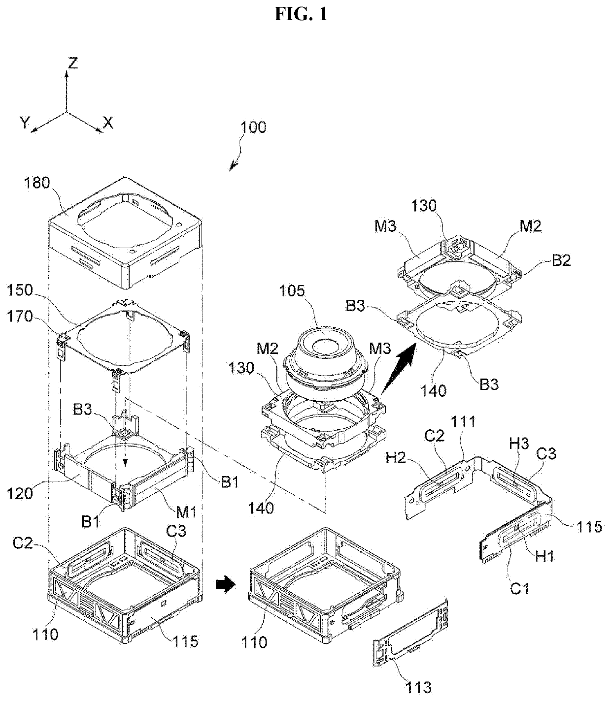
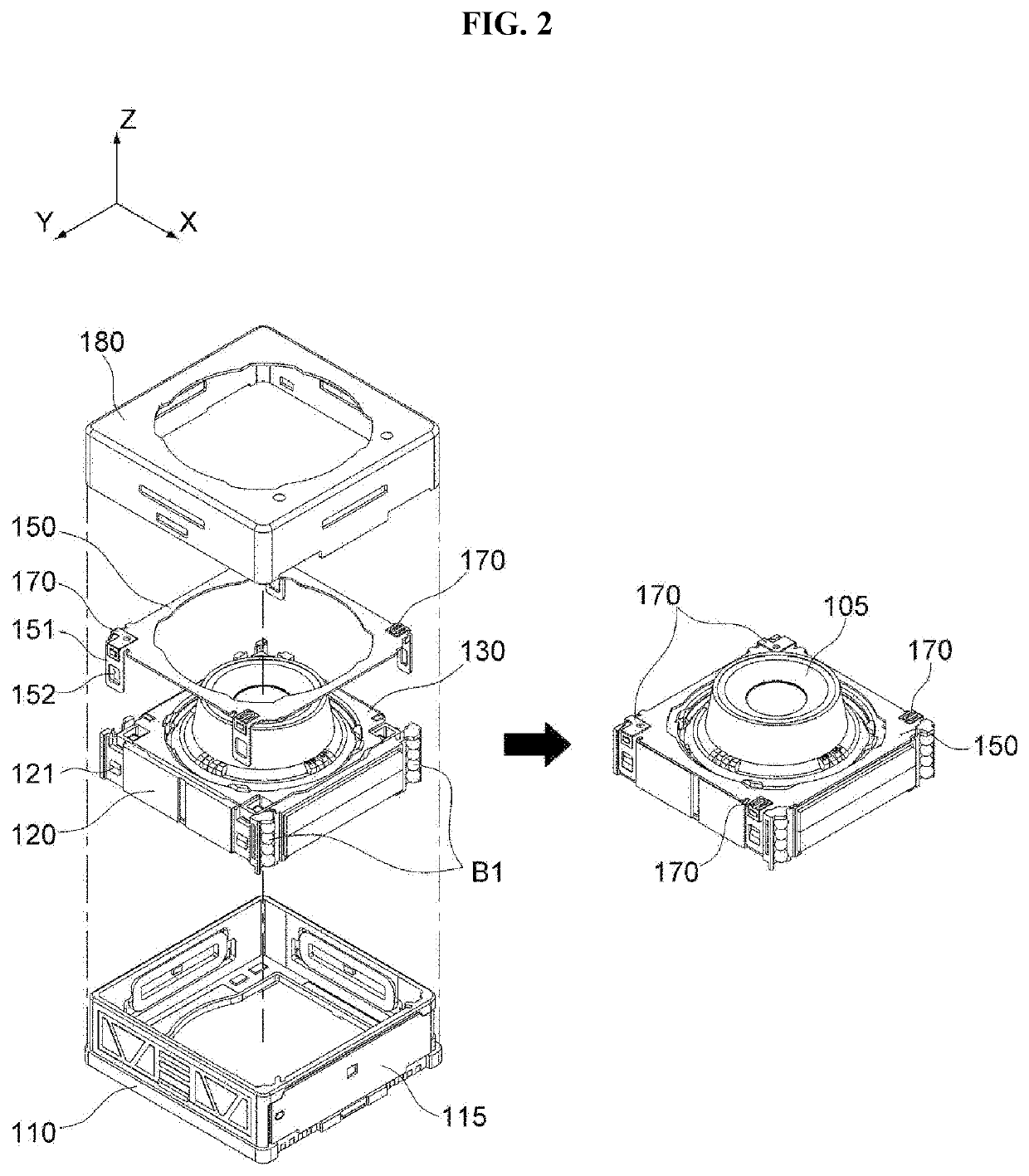
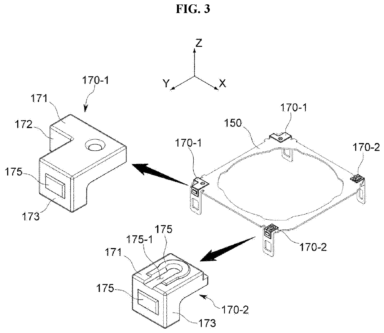
[0031]Hereinafter, preferred embodiments of the present disclosure will be described in detail with reference to the accompanying drawings. Prior to the description, it should be understood that the terms used in the specification and the appended claims should not be construed as limited to general and dictionary meanings, but interpreted based on the meanings and concepts corresponding to technical aspects of the present disclosure on the basis of the principle that the inventor is allowed to define terms appropriately for the best explanation.

[0032]Therefore, the description proposed herein is just a preferable example for the purpose of illustrations only, not intended to limit the scope of the disclosure, so it should be understood that other equivalents and modifications could be made thereto without departing from the scope of the disclosure.

[0033]FIG. 1 is an exploded view showing the configuration of an actuator 100 for a camera (hereinafter, referred to as an ‘actuator’) 1...


PUM


Abstract

An actuator for a camera according to an embodiment includes a base having an inner space formed therein, a carrier provided inside the base and configured to move in at least one direction among an optical axis direction, a first direction perpendicular to the optical axis and a second direction perpendicular to the optical axis and the first direction; and a damper provided to the carrier or the base and configured to have a shape extending in two or more directions among the optical axis direction, the first direction and the second direction.

Description

CROSS REFERENCE TO RELATED APPLICATIONS AND CLAIM OF PRIORITY[0001]This application claims benefit under 35 U.S.C. 119(e), 120, 121, or 365(c), and is a National Stage entry from International Application No. PCT / KR2020 / 008982, filed Jul. 9, 2020, which claims priority to the benefit of Korean Patent Application No. 10-2019-0086065 filed in the Korean Intellectual Property Office on Jul. 17, 2019, the entire contents of which are incorporated herein by reference.BACKGROUND1. Technical Field[0002]The present disclosure relates to a damper and an actuator for a camera including the same, and more particularly, to a damper capable of relieving multi-directional impacts and an actuator including the same.2. Background Art[0003]As the hardware technology for image processing has been developed and the user needs for image shooting have increased, functions such as autofocus (AF) and optical image stabilization (OIS) have been applied to a camera module or the like, mounted to a portable ...

Claims


Application Information

Patent Timeline
Patent Type & Authority Applications(United States)
IPC IPC(8): F16F15/04G02B27/64G03B5/00G03B13/36
CPCF16F15/04G02B27/646G03B2205/0007G03B13/36G03B5/00H04N23/60H04N23/685G02B7/09F16F1/373F16F15/08G03B3/10G03B5/02G03B30/00G03B2205/0015G03B2205/0053
Inventor KIM, HEE SEUNG
Owner JAHWA ELECTRONICS
Learn More