Display driving device

a driving device and display technology, applied in the direction of static indicating devices, cathode-ray tube indicators, instruments, etc., can solve the problems of source driver not recovering the clock, the level of input data may be changed, and the source driver cannot achieve the clock. the effect of preventing an image failure, minimizing the influence of external noise, and minimizing the change in the input data level attributable to external nois

Pending Publication Date: 2021-12-23
SILICON WORKS CO LTD
View PDF2 Cites 0 Cited by
  • Summary
  • Abstract
  • Description
  • Claims
  • Application Information

AI Technical Summary

Benefits of technology

[0007]Various embodiments are directed to providing a display driving device capable of preventing an image failure by minimizing the influence of external noise.
[0011]According to embodiments, when a lock fail attributable to external noise is detected, a common voltage having a fixed level is supplied to a node between the first and second terminating resistors disposed between the first and second data wires. Therefore, a change in a level of input data attributable to the external noise can be minimized.
[0012]Furthermore, embodiments can prevent an image failure by minimizing the influence of external noise on a common voltage.
[0013]Furthermore, embodiments can minimize a change in a voltage level of a node attributable to external noise by connecting a capacitor to a node between the first and second terminating resistors and thus can prevent an image failure.

Problems solved by technology

However, if external noise acts on the pair of data wires in common, a level of a common voltage formed in the terminating resistor may be changed.
If the level of the common voltage is changed due to the external noise, a level of the input data may deviate from an input range of a receiver of the source driver.
As a result, there is a problem in that the source driver does not recover the clock, the image data and the control data normally from the input data.

Method used


Image

  • Display driving device
  • Display driving device
  • Display driving device

Examples


first embodiment

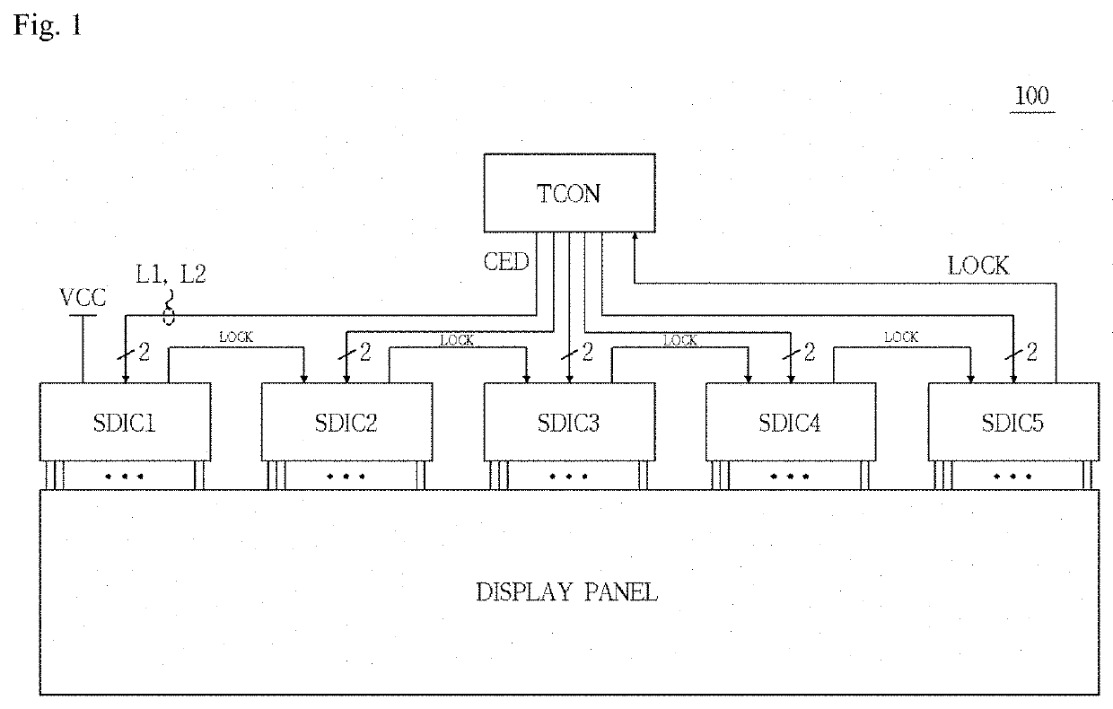
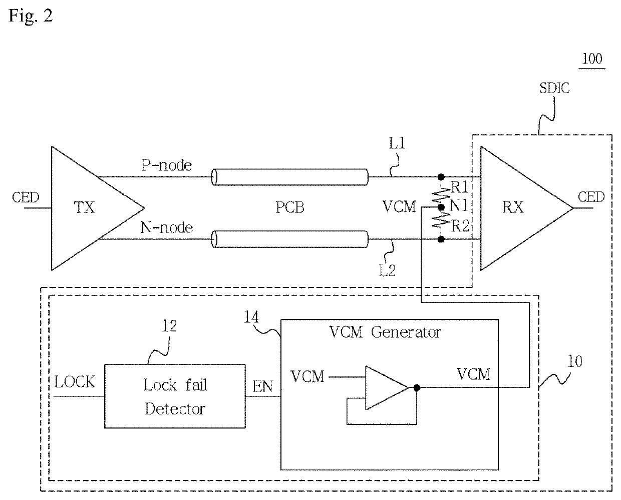
[0037]FIG. 2 is a block diagram of the display device 100 including a source driver SDIC according to a

[0038]Referring to FIG. 2, the display device 100 may include a transmitter TX of the timing controller TCON and the source driver SDIC.

[0039]The source driver SDIC may include a receiver RX and a noise reduction circuit 10.

[0040]The transmitter TX of the timing controller TCON and the receiver RX of the source driver SDIC may be connected through the pair of first and second data wires L1 and L2.

[0041]Furthermore, a first terminating resistor R1 may be configured at the termination of the first data wire L1. A second terminating resistor R2 may be configured at the termination of the second data wire L2. The first terminating resistor R1 and the second terminating resistor R2 are connected through a node N1. That is, the first terminating resistor R1 and the second terminating resistor R2 may be connected in series between the first and second data wires L1 and L2.

[0042]In this ca...

second embodiment

[0083]FIG. 6 is a block diagram of the display device 100 including a source driver SDIC according to a

[0084]Referring to FIG. 6, the source driver SDIC according to the second embodiment may include the receiver RX, the first terminating resistor R1, the second terminating resistor R2 and a capacitor C.

[0085]The receiver RX may be connected to the transmitter TX of the timing controller through the first and second data wires L1 and L2.

[0086]The first terminating resistor R1 and the second terminating resistor R2 may be disposed within a chip of the source driver SDIC. The first terminating resistor R1 and the second terminating resistor R2 may be connected in series between the first and second data wires L1 and L2.

[0087]The capacitor C may have one end connected to the node N1 between the first terminating resistor R1 and the second terminating resistor R2, and may have the other end connected to a terminal to which an external voltage Vx is applied. The external voltage Vx may h...

third embodiment

[0089]FIG. 7 is a block diagram of the display device 100 including a source driver SDIC according to a

[0090]Referring to FIG. 7, the source driver SDIC according to the third embodiment may include the receiver RX and the capacitor C.

[0091]The receiver RX may be connected to the transmitter TX of the timing controller through the first and second data wires L1 and L2.

[0092]In this case, the first terminating resistor R1 and the second terminating resistor R2 connected in series may be connected between the first and second data wires L1 and L2. The first terminating resistor R1 and the second terminating resistor R2 may be disposed in the printed circuit board PCB.

[0093]The capacitor C may have one end connected to the node N1 between the first terminating resistor R1 and the second terminating resistor R2 which are disposed in the printed circuit board PCB, and may have the other end connected to the terminal to which the external voltage Vx is applied.

[0094]The capacitor C may ac...


PUM


Abstract

The present disclosure discloses a display driving device insensitive to external noise. The display driving device may include first and second data wires configured to connect a transmitter of a timing controller and a receiver of a source driver, first and second terminating resistors configured to connect the first and second data wires, and a noise reduction circuit configured to detect a lock fail, generate a common voltage when detecting the lock fail, and provide the common voltage to a node between the first and second terminating resistors. The display driving device can prevent an image failure by minimizing the influence of external noise.

Description

BACKGROUND1. Technical Field[0001]The present disclosure relates to a display device, and more particularly, to a display driving device capable of preventing an image failure by minimizing the influence of external noise.2. Related Art[0002]In general, a display device may include a display panel, a gate driver, a source driver, a timing controller, etc. The timing controller may provide image data to the source driver. The source driver may provide the display panel with source signals corresponding to the image data.[0003]The timing controller and the source driver may be connected through a pair of data wires. For impedance matching, a terminating resistor may be disposed at the termination of the data wire.[0004]The timing controller may transmit, to the source driver, input data having a packet form and including a clock, image data and control data through the data wires. The source driver may recover the clock, the image data and the control data from the input data.[0005]Ho...

Claims


Application Information

Patent Timeline
Patent Type & Authority Applications(United States)
IPC IPC(8): G09G3/20G09G5/00
CPCG09G3/20G09G5/008G09G2310/0275G09G2330/12G09G2330/028G09G2330/08G09G3/006G09G2370/08G09G2330/06G09G3/2014G09G2310/08
Inventor KIM, YOUNG BOKKIM, WONG JONG
Owner SILICON WORKS CO LTD
Why Eureka
Try Eureka