Camera and radar sensor system and error compensation method thereof

a radar sensor and camera technology, applied in the field of camera and radar sensor system and an error compensation method thereof, can solve problems such as serious errors in data transmission

Pending Publication Date: 2022-07-14
MOVON CORP
View PDF10 Cites 0 Cited by
  • Summary
  • Abstract
  • Description
  • Claims
  • Application Information

AI Technical Summary

Problems solved by technology

These factors may be largely influenced by electromagnetic waves generated in the engine room and elec

Method used


Image

  • Camera and radar sensor system and error compensation method thereof
  • Camera and radar sensor system and error compensation method thereof
  • Camera and radar sensor system and error compensation method thereof

Examples


Embodiment Construction

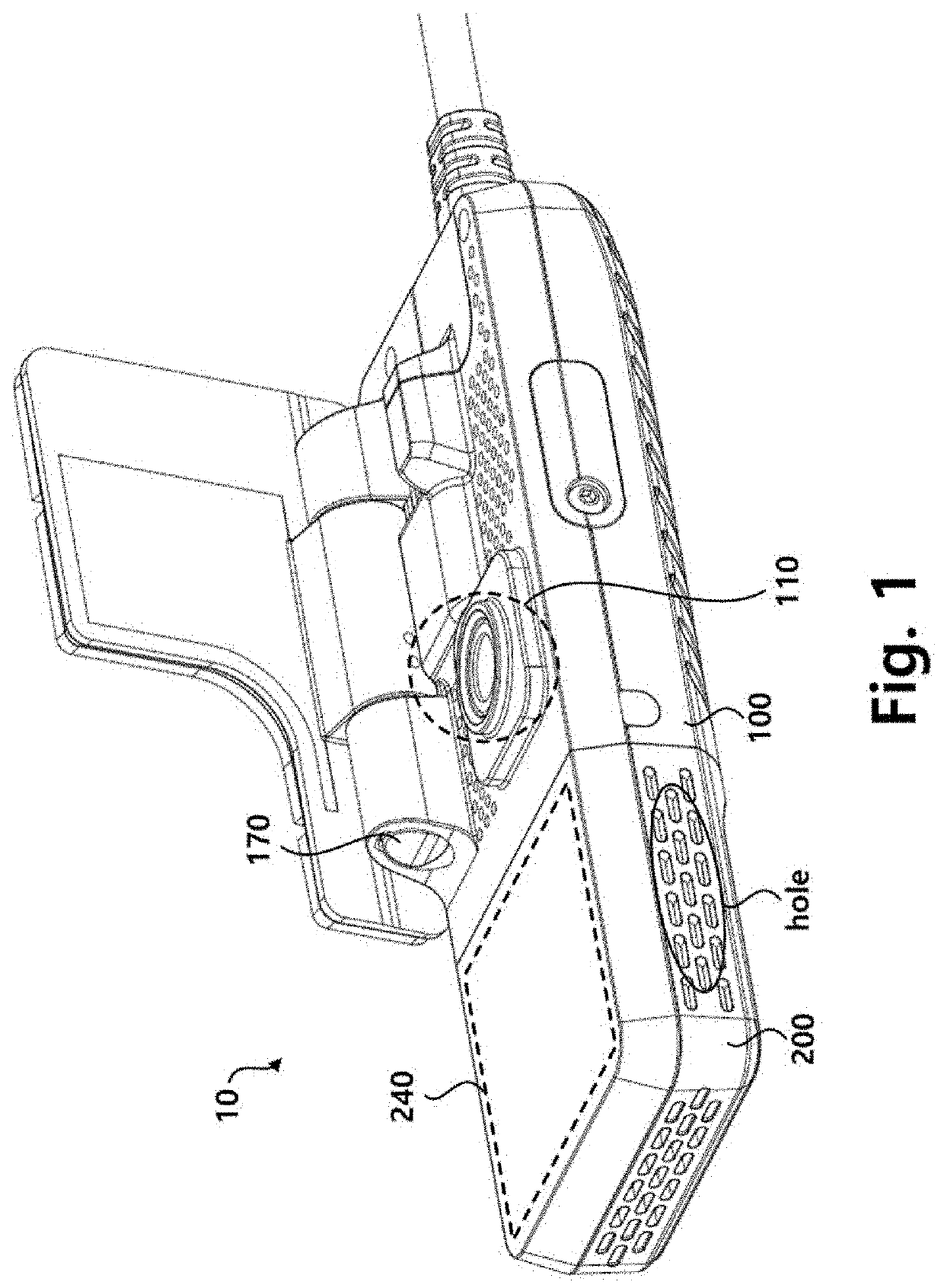
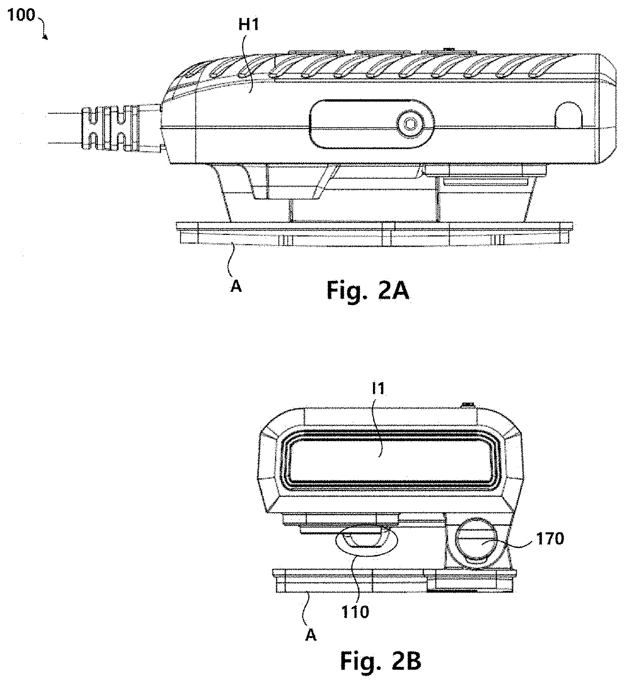
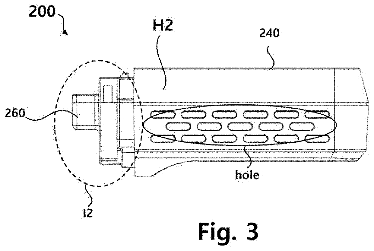
[0035]Hereinafter, a sensor system 10 according to the present embodiment will be described with reference to the accompanying drawings. FIG. 1 is a perspective view showing an overview of a sensor system 10 according to an embodiment. FIG. 2A is a diagram illustrating one side of a camera module 100. FIG. 2B is a diagram illustrating another side of the camera module 100. FIG. 3 is a diagram illustrating one side of a radar module 200.

[0036]Referring to FIGS. 1 to 3, the sensor system 10 according to the present embodiment includes the camera module 100 and the radar module 200. The camera module 100 is housed in a camera housing H1, and the radar module 200 is housed in a radar housing H2 different than the camera housing H1. The camera module 100 and the radar module 200, which are housed separately from each other, may be combined with each other to form the sensor system 10.

[0037]An imaging unit 110 of the camera module 100 captures an image of a moving direction of a vehicle a...


PUM


Abstract

A sensor system includes a camera module and a radar module, wherein the camera module and the radar module are housed separately and detachably, and the sensor system is mounted in a cabin of a vehicle.

Description

CROSS-REFERENCE TO RELATED APPLICATION[0001]This application claims priority to and the benefit of Korean Patent Applications of No. 10-2021-0003243, filed on Jan. 11, 2021 and No. 10-2021-0055139, filed on Apr. 28, 2021 and the disclosure of which is incorporated herein by reference in its entirety.BACKGROUND1. Field of the Invention[0002]The techniques set forth herein are related to a camera and radar sensor system and an error compensation method thereof.2. Discussion of Related Art[0003]Fatality rates of collision accidents occurring during high-speed driving of vehicles are high and such an accident may cause a chain collision accident leading to a big accident. Generally, forward collision accidents occur due to a failure to keep a sufficient distance between vehicles to avoid collision due to drivers' carelessness or difficulties in securing a field of view that is caused by bad weather. In particular, a driver's limited visual ability and a response delay time required to r...

Claims


Application Information

Patent Timeline
IPC IPC(8): G01S13/86G06T7/70G06T7/20H04N5/247G06T7/50H04N17/00G01S13/931B60R11/04
CPCG01S13/867G06T7/70G06T7/20H04N5/247B60R2011/0026H04N17/002G01S13/931B60R11/04G06T2207/30252G06T7/50G01S7/40G01S7/497G01S17/931G01S13/87G01S7/4026G01S7/027G01S7/4086G01S7/4021G01S7/003G01S2013/93276G01S7/2955G06T7/80G06T2207/10024G06T2207/10028H04N23/45H04N23/57H04N23/55H04N23/51B60W50/029B60W40/02B60W30/08B60R11/00G03B17/48G03B30/00B60W2050/0215B60W2420/42B60W2420/52B60Q9/008B60R2011/0078H04N23/90
Inventor CHUNG, YOUNKYUPARK, YONG JEONGCUI, CHENGLINYOON, PYOUNGHWASEO, HYUN WOO
Owner MOVON CORP
Why Eureka
Try Eureka