
Determination of the average distance between a measurement device and a conductor

a measurement device and average distance technology, applied in the direction of instruments, mechanical equipment, transportation and packaging, etc., can solve the problems of insufficient accuracy, inability to measure the depth of cover over thousands of kilometers, and inability to record relative old pipeline installations

Pending Publication Date: 2022-08-04
SIEMENS ENERGY GLOBAL GMBH & CO KG
View PDF0 Cites 0 Cited by
  • Summary
  • Abstract
  • Description
  • Claims
  • Application Information

AI Technical Summary

Benefits of technology

The patent is about a method for measuring the position of a device on a pipeline. The method uses the ratio of the vertical to horizontal component of the device's profile to determine its position. This ratio is independent of the strength of the current being measured, so the results are accurate even if the current is not very strong. The method also includes compiling best-fit lines to account for variations in the device's vertical position, which helps minimize the impact of external factors on the position determination.

Problems solved by technology

In particular relatively old pipeline installations, however, were not recorded or were not recorded with sufficient accuracy during the laying.
Measurement of the depth of cover over thousands of kilometers, however, is not practicable because of the manual outlay.
The crucial disadvantages of this technology are on the one hand the dependency of the usability on the ground condition (for example difficulties when there is moisture in the ground) and on the other hand the strong reflection of the signal on the Earth's surface as soon as the system is used some distance away from the ground.
This error behavior cannot trivially be compensated for by external and therefore absolute measurements owing to the lack of contact with the outside world.
This is contributed to by the aspect of the usually metallic structure of the pipeline, which interferes (Faraday Cage) with the transmission of radio signals (electric fields).
This form of sensor technology is however normally not present, particularly in poorly calibrated old installations.
Besides the drift behavior, a further disadvantage is also the fact that certain types of pipelines are fundamentally not piggable.
In which case, in tests, all methods based on the VLF method have been found to be insufficiently accurate or insufficiently practicable.
The depth estimation on the basis of the full width at half maximum of the measurement curve is not, however, sufficiently accurate to satisfy the requirements of the pipeline operators in developed economies.

Method used


Image

  • Determination of the average distance between a measurement device and a conductor
  • Determination of the average distance between a measurement device and a conductor
  • Determination of the average distance between a measurement device and a conductor

Examples


Embodiment Construction

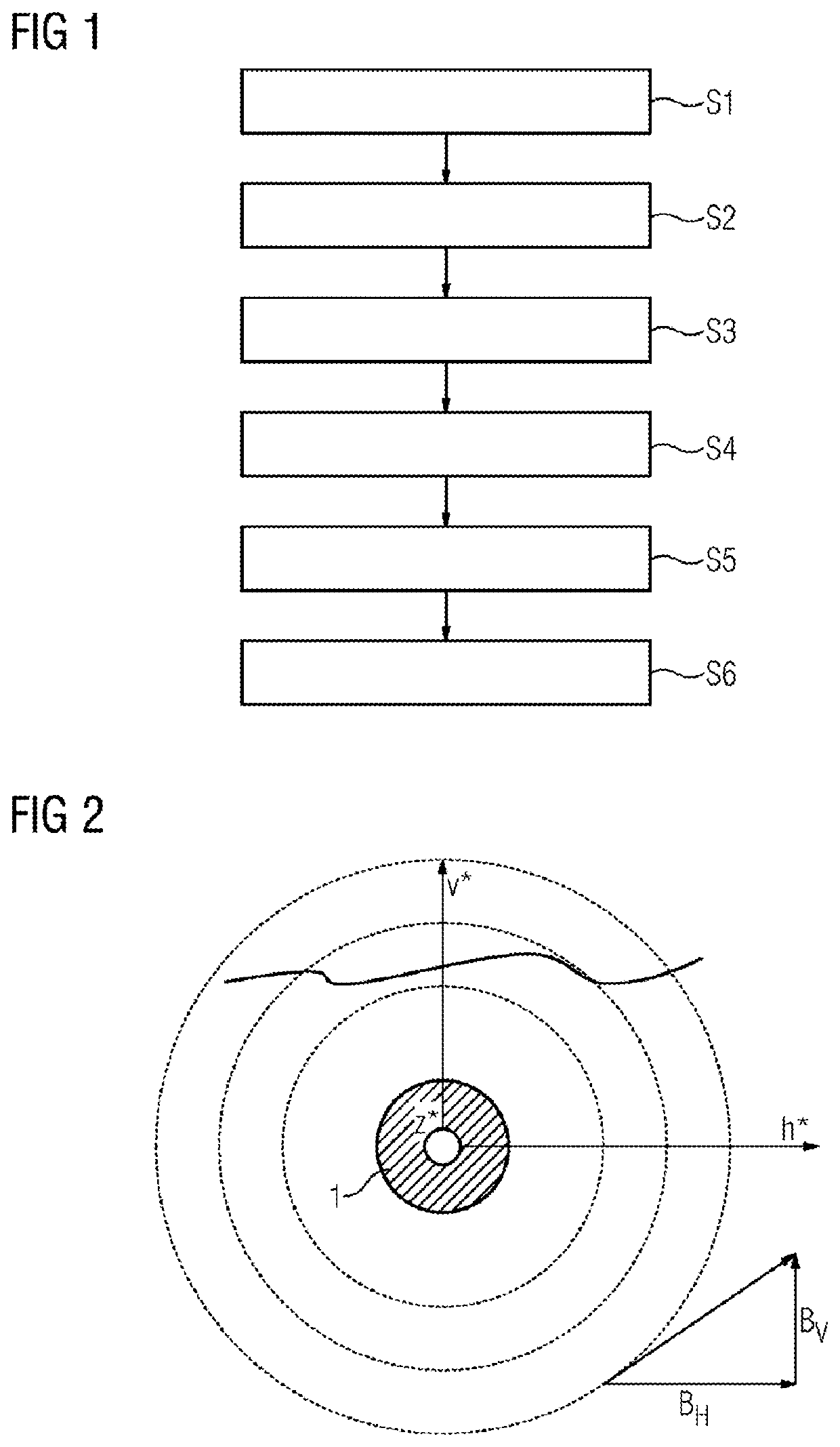
[0047]FIG. 1 shows a flowchart of the steps S1-S6 of the method according to the invention for determining the average distance of a measuring device from a conductor, wherein the measuring device comprises a measuring system, wherein an electrical current flows through the conductor, so that a magnetic field having a magnetic flux density is formed, the magnetic flux density having a horizontal component and a vertical component.

[0048]The steps of the method are in detail:—method step S1: determining a profile of the horizontal component against the horizontal position of the measuring device, the horizontal position indicating the orthogonal distance of the measuring device from the longitudinal axis of the conductor parallel to the Earth's surface, the profile of the horizontal component being determined by measuring the horizontal components at at least two different horizontal positions using the measuring system of the measuring device, which changes the horizontal position, a...


PUM


Abstract

A method for determining the average distance between a measurement device and a conductor includes determining a profile of a horizontal component using the horizontal position of the device that indicates the orthogonal distance between the device and the longitudinal axis of the conductor parallel to the earth's surface, measured at at least two different horizontal positions, determining a profile of the vertical component, which is associated with the determined profile of the horizontal component, using the horizontal position of the device, wherein the vertical profile is determined by measuring the vertical components associated with the horizontal components, determining the ratio of the profiles as a function using the horizontal position of the device, determining the derivative of the ratio according to the horizontal position, determining the reciprocal of the derivative, and determining the average distance between the devices and the conductor from the reciprocal of the derivative.

Description

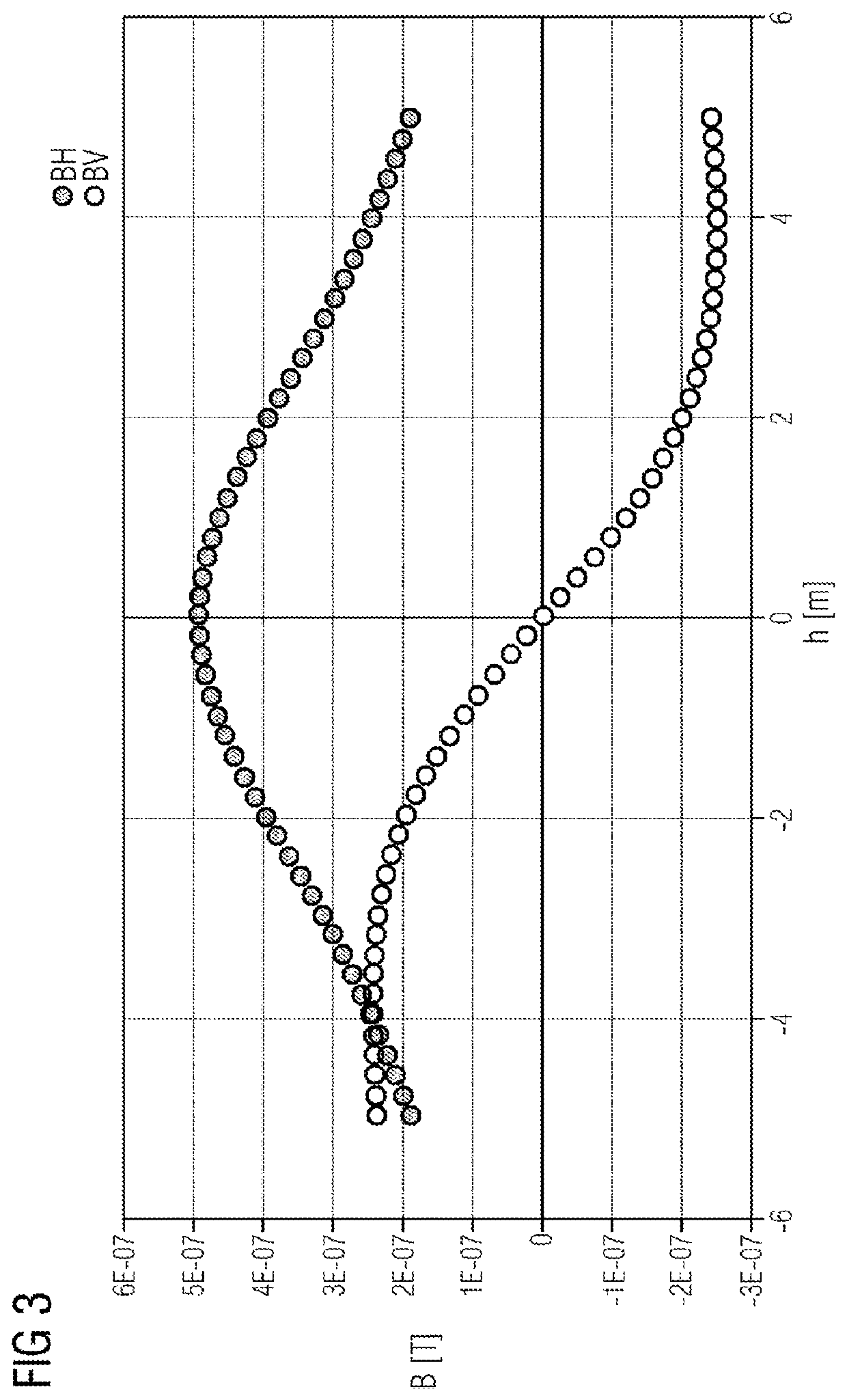
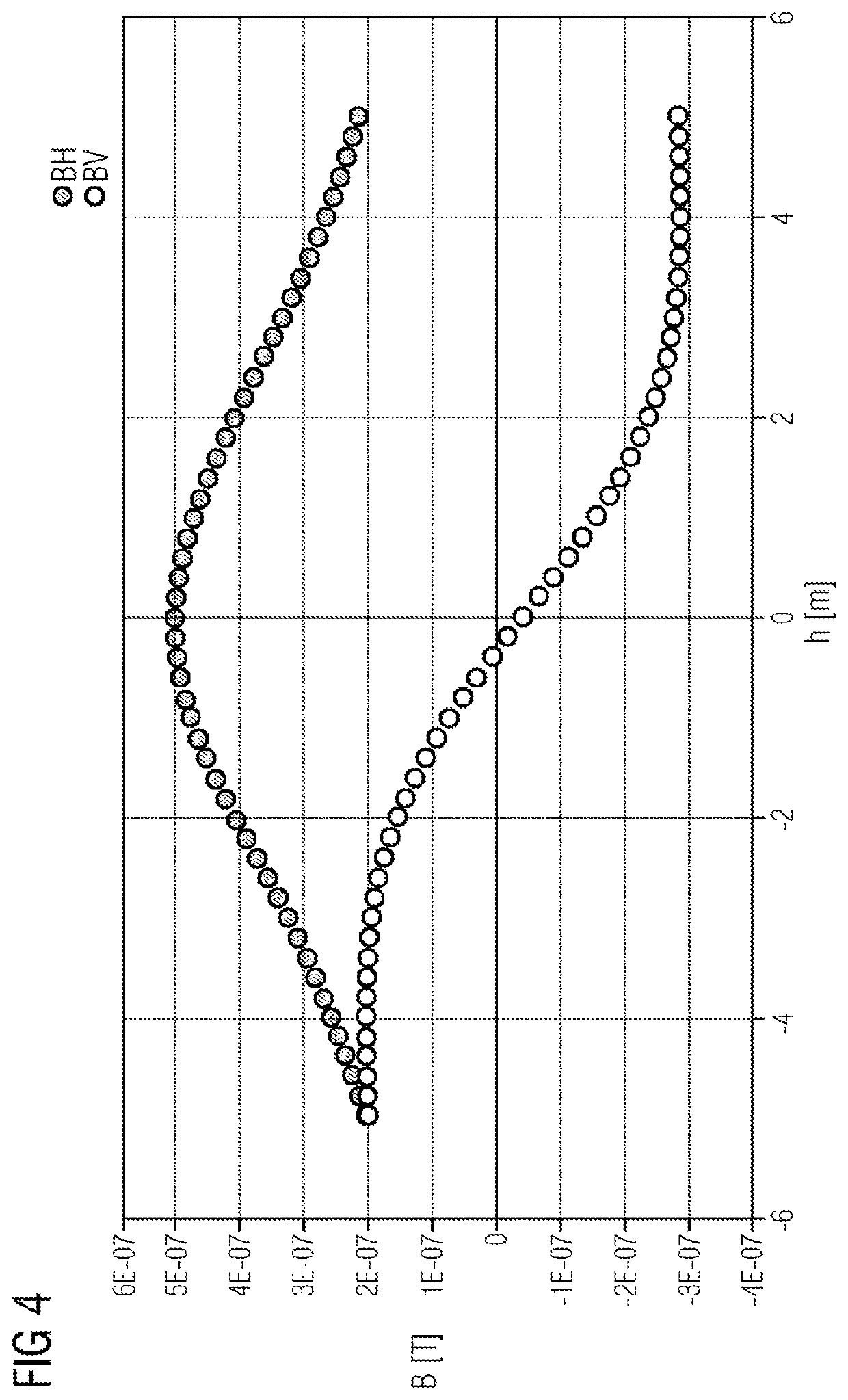
CROSS REFERENCE TO RELATED APPLICATIONS[0001]This application is the US National Stage of International Application No. PCT / EP2020 / 066622 filed 16 Jun. 2020, and claims the benefit thereof. The International Application claims the benefit of European Application No. EP19183605 filed 1 Jul. 2019. All of the applications are incorporated by reference herein in their entirety.FIELD OF THE INVENTION[0002]The present invention relates to a method for determining the distance of a measuring device from a conductor. The invention furthermore provides a measuring device. The invention may, in particular, be used to determine the depth of the location of a pipeline below the Earth's surface.BACKGROUND OF INVENTION[0003]Pipelines for transporting oil and gas are critical supply infrastructures and need to be monitored over thousands of kilometers. The majority of these pipelines runs underground, typically at a burying depth of 1.5-3 meters. One important inspection criterion is the regular d...

Claims


Application Information

Patent Timeline
IPC IPC(8): G01B7/02G01D5/20G01B7/26F17D5/00B64C39/02
CPCG01B7/023G01D5/20G01B7/26B64C2201/12B64C39/024B64C2201/027F17D5/005G01V3/16G01V3/081G01V3/104B64U10/13B64U2101/60B64U2101/00
Inventor WEISS, ROLANDLIEPE, MIKEWAKOLBINGER, STEFAN
Owner SIEMENS ENERGY GLOBAL GMBH & CO KG
Learn More