Map information system

a map and information system technology, applied in navigation instruments, instruments, transportation and packaging, etc., can solve the problems of insufficient accuracy of reliability calculation based on brightness distribution and high reliability, and achieve high accuracy, high accuracy, and increase in accuracy (quality)

Active Publication Date: 2020-04-09
TOYOTA JIDOSHA KK
View PDF0 Cites 1 Cited by
  • Summary
  • Abstract
  • Description
  • Claims
  • Application Information

AI Technical Summary

Benefits of technology

[0008]An object of the present disclosure is to provide a technique that can increase accuracy of road marking map information that is used for driving support control and indicates a position of a specific road marking.
[0019]According to the present disclosure, the database management device detects the road marking candidate around the vehicle, and determines the evaluation value that indicates certainty of the detected road marking candidate being the specific road marking. More specifically, the database management device recognizes the vehicle behavior of at least one of the vehicle and another vehicle in a period when passing the road marking candidate, based on the driving environment information. The vehicle behavior with respect to the specific road marking is totally different from the vehicle behavior with respect to other road markings (for example, a lane marking). Therefore, using the vehicle behavior makes it possible to determine the evaluation value regarding the specific road marking with high accuracy. The evaluation value being determined with high accuracy causes increase in accuracy (quality) of the road marking map information that is automatically generated based on the evaluation value. Since the accuracy of the road marking map information is increased, accuracy of the driving support control using the road marking map information also is increased.

Problems solved by technology

However, accuracy of the reliability calculation based on the brightness distribution is insufficient.
For example, a white line defining a lane is erroneously detected as a stop line, and furthermore its reliability is erroneously determined to be high.

Method used


Image

  • Map information system
  • Map information system
  • Map information system

Examples


first example

4-1. First Example

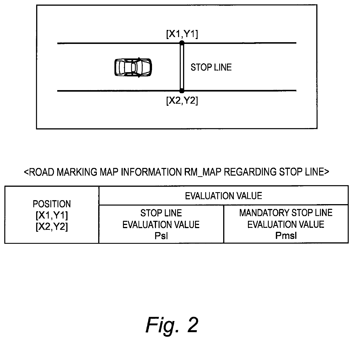
[0118]FIGS. 11 and 12 are conceptual diagrams for explaining a first example. In the first example, we consider the “stop line candidate” being a candidate for the stop line SL. The stop line evaluation value Psl indicates certainty of the stop line candidate being the stop line SL. It should be noted that the stop line SL here includes the mandatory stop line.

[0119]FIG. 11 shows a situation where the vehicle 1 passes the stop line SL. In general, a trajectory TR of the vehicle 1 passing the stop line SL is almost orthogonal to a longitudinal direction L of the stop line SL. In other words, an angle θ between the trajectory TR of the vehicle 1 and the longitudinal direction L of the stop line SL is close to 90 degrees. On the other hand, FIG. 12 shows another situation where the vehicle 1 crosses a center line CL. An angle θ between the trajectory TR of the vehicle 1 and a longitudinal direction L of the center line CL is small. Therefore, it is possible to determi...

second example

4-2. Second Example

[0121]A second example is a modification example of the first example. In the second example, a trajectory TR of another vehicle 2 (see FIG. 4) instead of the vehicle 1 is used. More specifically, the database management device 30 recognizes the trajectory TR of another vehicle 2 passing the stop line candidate as the vehicle behavior, based on the surrounding situation information 210. Then, the database management device 30 calculates an angle θ between the trajectory TR of said another vehicle 2 and the longitudinal direction L of the stop line candidate. The database management device 30 increases the stop line evaluation value Psl as the angle θ is closer to 90 degrees. In other words, the database management device 30 calculates the stop line evaluation value Psl to be higher as the angle θ is closer to 90 degrees.

third example

4-3. Third Example

[0122]FIGS. 13 and 14 are conceptual diagrams for explaining a third example. In the third example, we consider the mandatory stop line MSL. The mandatory stop line evaluation value Pmsl indicates certainty of the stop line candidate being the mandatory stop line MSL. When the vehicle 1 passes the stop line candidate, the database management device 30 determines the mandatory stop line evaluation value Pmsl in addition to the stop line evaluation value Psl described in the above first and second examples.

[0123]FIG. 13 shows a speed when the vehicle 1 passes the mandatory stop line MSL. The vehicle 1 is required to always stop before the mandatory stop line MSL. Therefore, the speed of the vehicle 1 on the mandatory stop line MSL is generally low. On the other hand, FIG. 14 shows a speed when the vehicle 1 passes the stop line SL other than the mandatory stop line MSL. The vehicle 1 does not necessarily stop before the stop line SL. It is therefore possible to deter...


PUM


Abstract

A map information system includes a database management device configured to manage a map database used for vehicle driving support control. The map database includes road marking map information that indicates a position of a specific road marking including at least one of a stop line and a pedestrian crossing. The database management device is further configured to: detect a road marking candidate being a candidate for the specific road marking around a vehicle; recognize vehicle behavior of at least one of the vehicle and another vehicle in a period when passing the road marking candidate; determine, based on the vehicle behavior, an evaluation value that indicates certainty of the road marking candidate being the specific road marking; and register the road marking candidate having the evaluation value equal to or higher than a threshold, as the specific road marking, in the road marking map information.

Description

BACKGROUNDTechnical Field[0001]The present disclosure relates to a technique that manages map information used for driving support control that supports driving of a vehicle.Background Art[0002]Patent Literature 1 discloses a vehicle control device installed on a vehicle. The vehicle control device images a road surface ahead of the vehicle by using a camera. The vehicle control device analyzes the road surface image to detect a stop line on the road surface. Moreover, the vehicle control device calculates reliability of the detected stop line being actually present, based on brightness distribution of a plurality of points included in the road surface image. When the reliability is equal to or higher than a predetermined value, the vehicle control device executes vehicle travel control required for stopping the vehicle before the detected stop line.[0003]Patent Literature 2 discloses a traffic information providing system. The traffic information providing system includes an in-veh...

Claims


Application Information

Patent Timeline
Patent Type & Authority Applications(United States)
IPC IPC(8): G01C21/32G06F16/29G06K9/00B60W30/095
CPCG06K9/00825G06F16/29G06K9/00798G01C21/32B60W30/0956G01C21/3811B60W30/08B60W30/12B60W2552/53B60W2540/10B60W2540/12B60W2540/18G06V20/588G01C21/387G01C21/3815G06V20/584
Inventor HOKAI, KEISUKEHAYASHI, YUSUKEKAMATA, NOBUHIDE
Owner TOYOTA JIDOSHA KK
Why Eureka
Try Eureka