Angular and axial position sensor arrangement

a sensor arrangement and axial position technology, applied in the field of angular and axial position sensor arrangement, can solve the problem of very limited volume, and achieve the effect of reasonable cost and minimal space and computational power

Active Publication Date: 2016-01-26
THE SWATCH GRP RES & DEVELONMENT LTD
View PDF6 Cites 65 Cited by
  • Summary
  • Abstract
  • Description
  • Claims
  • Application Information

AI Technical Summary

Benefits of technology

[0006]The purpose of the present invention is to provide a combined angular and axial position sensor arrangement that requires a minimum of space and computational power, which can be implemented in a robust way in electronic products, and which can be manufactured at reasonable cost.
[0017]The axial detection encoded rings are provided with a simple coding pattern. The first N−1 axial detection encoded rings entirely consist of value A, and the ultimate Nth axial detection encoded ring entirely consists of value B. This coding pattern permits the measurement of the axial position of the encoded member by the sensors.
[0019]Since the axial detection encoded rings form a rotation invariant axial pattern of the encoded member, the said pattern may be detected by an array of sensors aligned parallel to the encoded member. In this way, various sensors originally implemented for angular position determination may also serve to determine the axial position of the encoded member, making a separate axial detection arrangement unnecessary because the same sensors can be used to determine both the angular and the axial position of the encoded member. As a consequence, a respective angular and axial position sensor arrangement can be realized in a space- and cost-saving way.
[0022]Advantageously the angular and axial position sensor arrangement is conceived to be mounted in an electronic watch to provide reliable measurement of the axial and angular position of a crown. The sensor arrangement can tolerate any mechanical play inherent in such an arrangement.

Problems solved by technology

In watch applications, volume is very limited.
So this sensor arrangement of the prior art occupies a large space inside the watch case, which is a drawback.

Method used


Image

  • Angular and axial position sensor arrangement
  • Angular and axial position sensor arrangement
  • Angular and axial position sensor arrangement

Examples


first embodiment

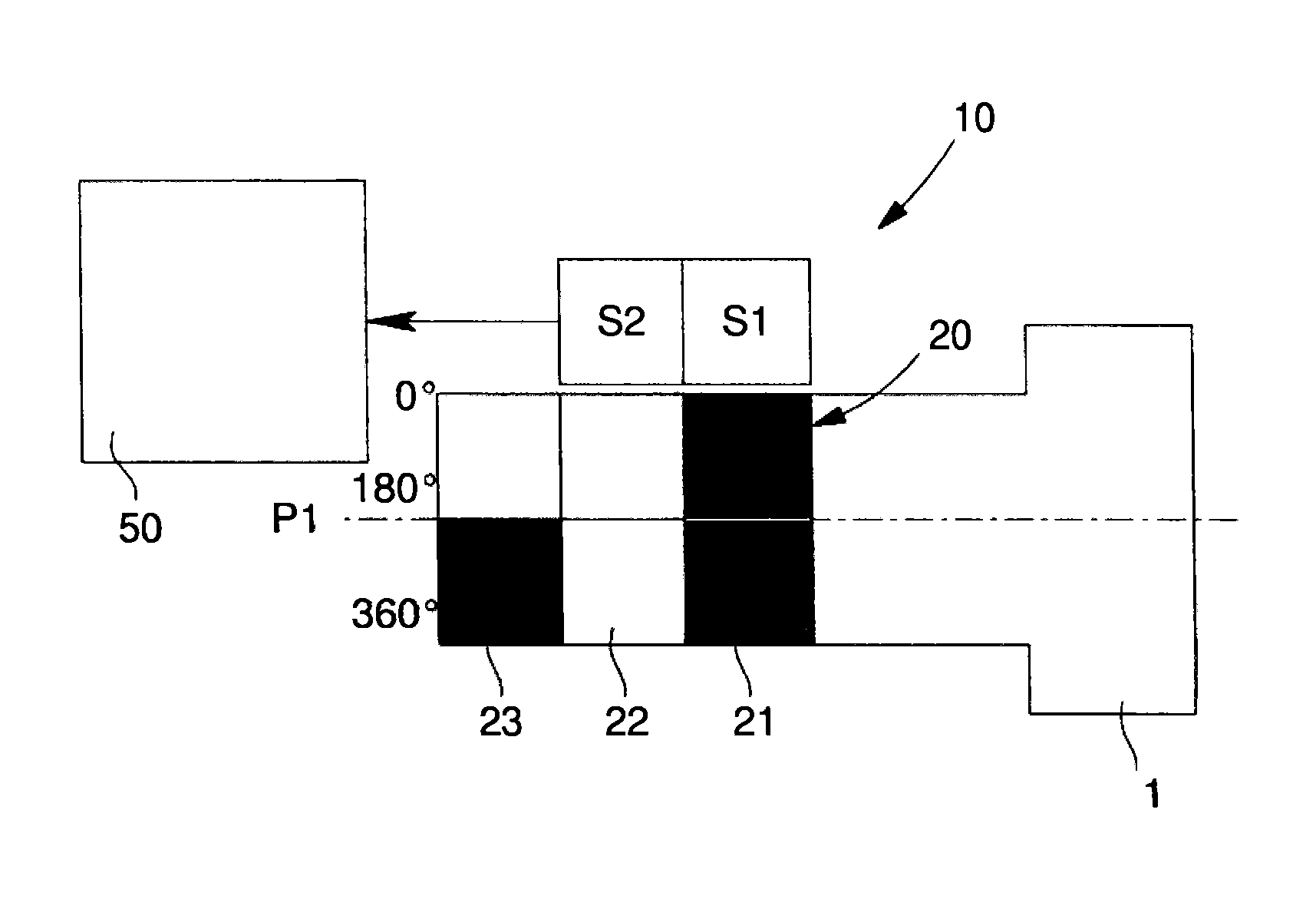
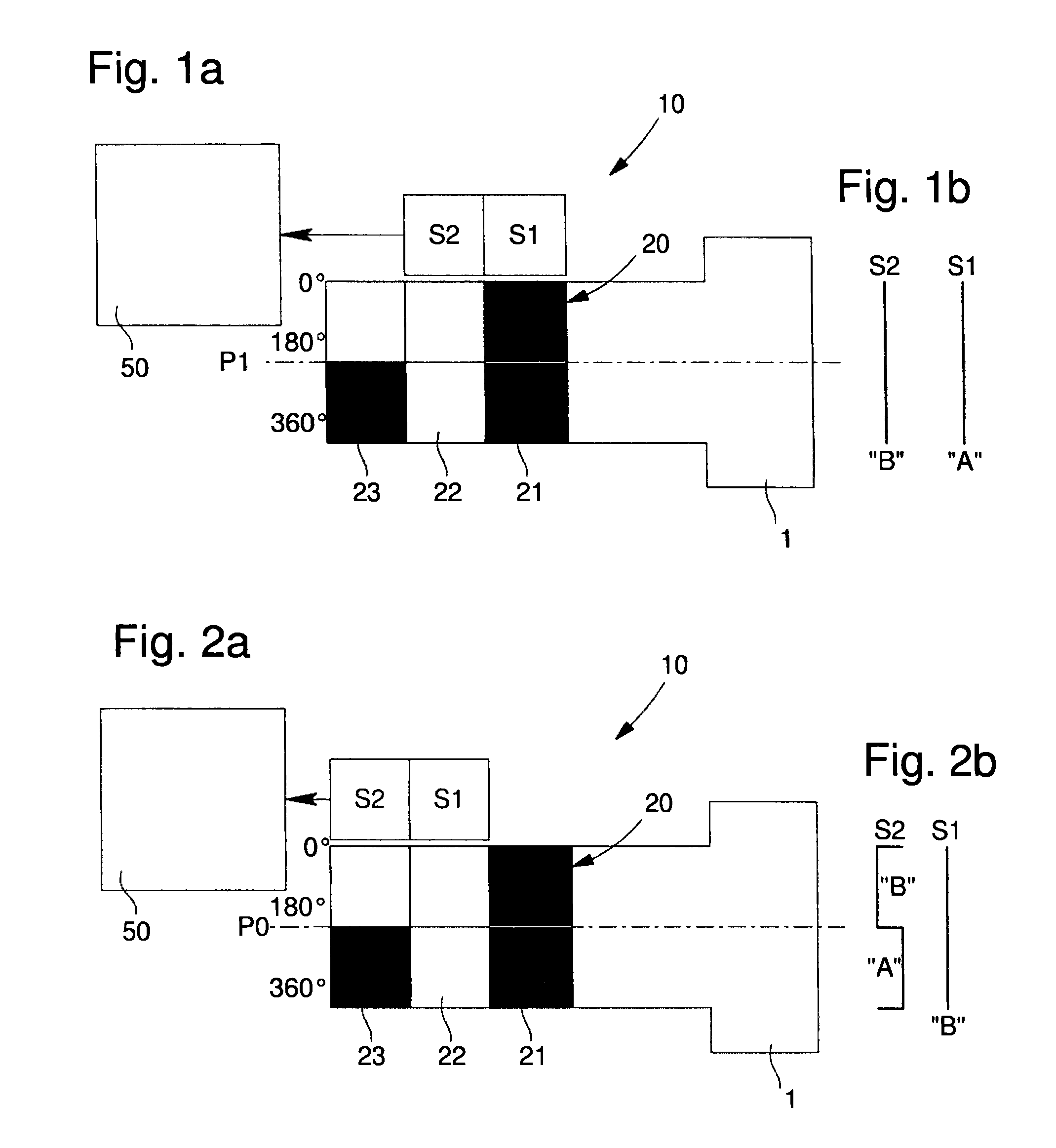
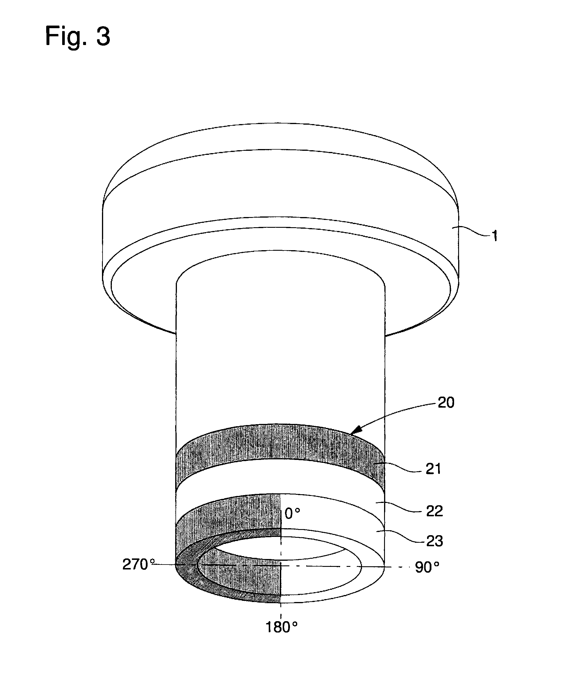
[0079]In the initial configuration as illustrated in FIGS. 1a and 2a, the encoded member 20 comprises a first axial detection encoded ring 21, illustrated as the rightmost vertical stripe. The encoded member 20 further comprises a second axial detection encoded ring 22 as indicated by the central vertical stripe in FIGS. 1a and 2a. Moreover, the encoded member comprises an angular detection encoded ring 23 axially adjacent to the second axial detection encoded ring 22. In this first embodiment, the number N of axial detection encoded rings is two, and the number M of angular detection encoded ring is one.

[0080]As illustrated in FIGS. 1a and 2a, the first axial detection encoded ring 21 includes two sections each distributed on 180° of the circumference. Each of these sections is coded with value A, as indicated by illustrating them in black, to be detected by at least one sensor overlapping said first axial detection encoded ring 21. The second axial detection encoded ring 22 compri...

second embodiment

[0088]In FIGS. 4a to 6a, the combined angular and axial position sensor arrangement 10 is shown, in which three sensors S1, S2, S3 are arranged adjacently in a row of sensors. Said row of sensors S1, S2, S3 is aligned parallel to the axis of the encoded member. The encoded member 20 comprises three axial detection encoded rings 21, 21′, 22 axially arranged, and two angular detection encoded rings 23, 23′ axially arranged. First and second axial detection encoded rings 21, 21′ are with value A along their entire circumference, whereas the third axial detection encoded ring 22 is with value B along its entire circumference. With these three axial detection encoded rings, the measurement unit 50 connected to the three sensors can determine three axial positions of the encoded member, from the first axial position where the first sensor S1 overlaps the first axial detection encoded ring 21 to the third axial position where the first sensor S1 overlaps the third axial detection encoded r...

third embodiment

[0099]In FIGS. 7a to 10a, the combined angular and axial position sensor arrangement 10 is shown, in which four sensors S1, S2, S3 and S4 are arranged adjacently in a row of sensors. Said row of sensors S1, S2, S3, S4 is aligned parallel to the axis of the encoded member 20. The encoded member comprises four axial detection encoded rings 21, 21′, 21″, 22 axially arranged, and also three angular detection encoded rings 23, 23′, 23″ axially arranged. First, second and third axial detection encoded rings 21, 21′, 21″ are with value A along their entire circumference, whereas the fourth axial detection encoded ring 22 is with value B along its entire circumference. With these four axial detection encoded rings, the measurement unit 50 connected to the sensors can determine four axial positions of the encoded member, from the first axial position where the first sensor S1 overlaps the first axial detection encoded ring 21 to the fourth axial position where the first sensor S1 overlaps th...


PUM


Abstract

The angular and axial position sensor arrangement includes several sensors arranged adjacently, and aligned parallel to the axis of an encoded member that is angularly and axially displaceable relative to the sensors. The encoded member includes N−1 axial detection encoded rings with value A along their entire circumference and includes an Nth axial detection encoded ring that is axially adjacent with value B, different from value A, along its entire circumference. The values of axial detection encoded rings are distinguishable by the sensors overlapping some axial detection encoded rings. The encoded member includes several angular detection encoded rings axially adjacent to the Nth axial detection encoded ring. The angular detection encoded rings include a coding pattern composed of A and B values along their circumference to determine angular position by some sensors overlapping them.

Description

[0001]This application claims priority from European Patent Application No. 13197208.5 filed 13 Dec. 2013, the entire disclosure of which is incorporated herein by reference.FIELD OF THE INVENTION[0002]The present invention relates to a sensor arrangement adapted for detecting and determining angular as well as axial positions of an encoded member being rotatable as well as axially displaceable relative to a series of at least two sensors.BACKGROUND AND PRIOR ART[0003]Generally, incremental or absolute encoding schemes can be used to measure the angular position of a rotating device, such as a volume-control knob or the crown of an electronic watch. In many applications, such control elements are also axially displaceable in order to trigger or to activate various functions of a device. Therefore, it is also necessary to measure the axial position of the same knob or crown. In watch applications, the axial position of the crown is used to change the modes of the watch, such as show-...

Claims


Application Information

Patent Timeline
Patent Type & Authority Patents(United States)
IPC IPC(8): H03M1/22G04C3/00G04B27/02G01D5/245G01D5/347
CPCG04C3/007G01D5/245G01D5/3473G01D5/34746G04B27/02G04C3/004G01D2205/90
Inventor HOOVER, DAVIDFERRI, YVAN
Owner THE SWATCH GRP RES & DEVELONMENT LTD
Why Eureka
Try Eureka