Supercharge Your Innovation With Domain-Expert AI Agents!

Changing a display mode for a graphical user interface

a graphical user interface and display mode technology, applied in the field of changing the display mode can solve the problems of compromising the privacy of users utilizing and affecting the use of the graphical user interface. wide viewing angles may compromise the privacy of users,

Inactive Publication Date: 2016-02-02
INT BUSINESS MASCH CORP
View PDF12 Cites 2 Cited by
  • Summary
  • Abstract
  • Description
  • Claims
  • Application Information

AI Technical Summary

Benefits of technology

This patent is about a way to change the display mode of an apparatus. The apparatus has a screen that can show different display modes, like a passive matrix display mode and an active matrix display mode. The apparatus also has a switch that can change the display mode from one mode to another. The technical effect of this invention is to provide a convenient way for users to change the display mode of the apparatus, which can improve the user experience.

Problems solved by technology

Graphical user interface technology has evolved due to a number of factors, including spatial limitations, power consumption, weight, image quality, response time, color gamut, and viewing angle.
Because the display of some current graphical user interfaces may be viewed from wide viewing angles, the privacy of the user utilizing the graphical user interface may be compromised.
For example, when viewed at angles greater than the viewing angle, the image displayed by a graphical user interface may appear poorly saturated, darkened, garbled, faint, blurry, or have poor contrast.
Wide viewing angles may compromise the privacy of a user utilizing a graphical user interface by allowing persons other than the user to view the graphical user interface.
In another example, secure information may be compromised if unauthorized persons are allowed to view, from a large viewing angle, data emitted from a graphical user interface.
However, although such screen are designed to block viewing outside of a predetermined viewing angle, such screen also cause an unacceptable degradation in image quality inside of the viewing angle as well.
For example, the brightness of the image inside of the viewing angle may be severely compromised.
Also, the currently used screens must be inconveniently transported and kept near the graphical user interface.
These screens may also become blurry or scratched over time.

Method used


Image

  • Changing a display mode for a graphical user interface
  • Changing a display mode for a graphical user interface
  • Changing a display mode for a graphical user interface

Examples


Embodiment Construction

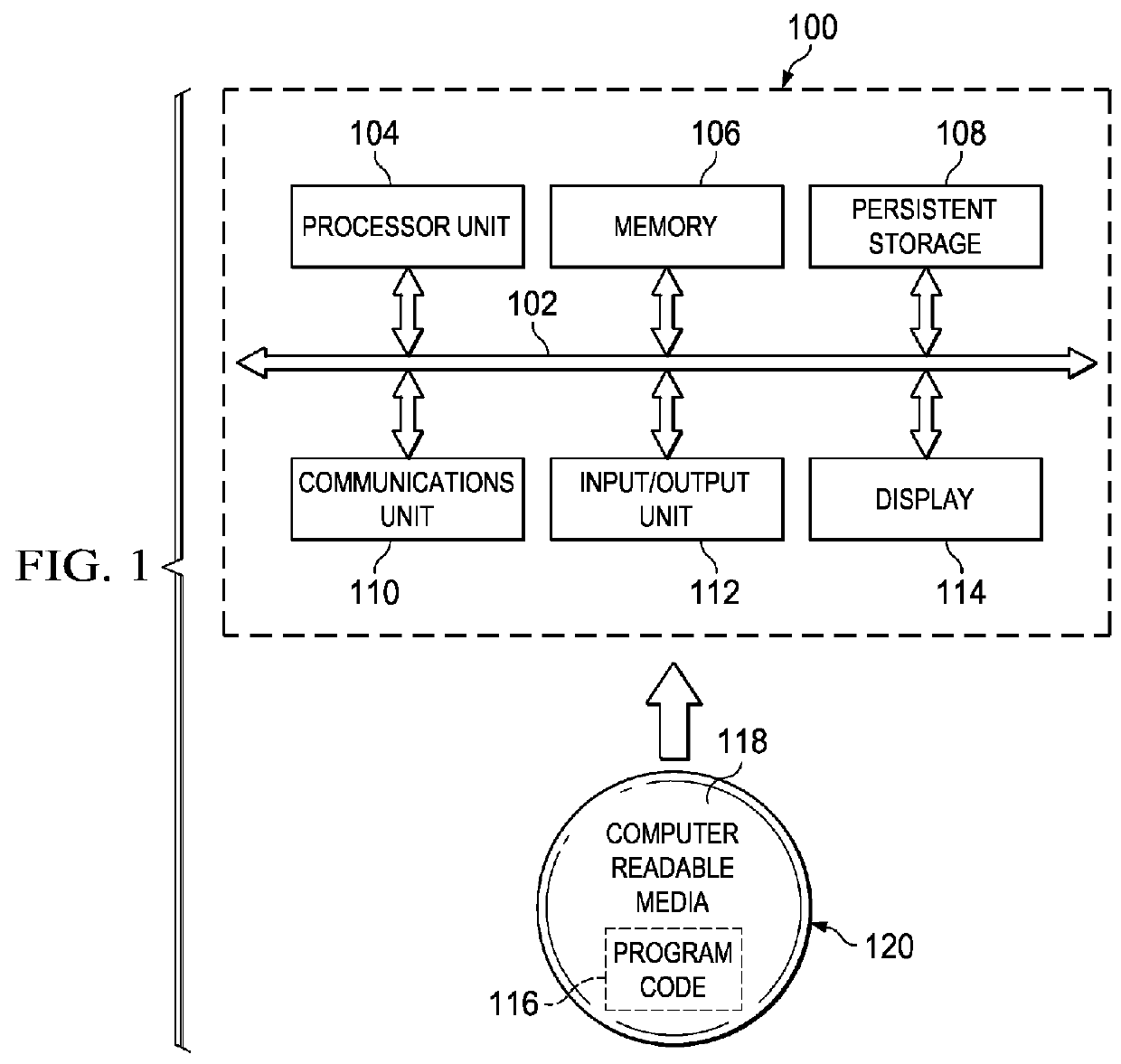
[0019]Turning now to FIG. 1, a diagram of a data processing system is depicted in accordance with an illustrative embodiment of the present invention. In this illustrative example, data processing system 100 includes communications fabric 102, which provides communications between processor unit 104, memory 106, persistent storage 108, communications unit 110, input / output (I / O) unit 112, and display 114.

[0020]Processor unit 104 serves to execute instructions for software that may be loaded into memory 106. Processor unit 104 may be a set of one or more processors or may be a multi-processor core, depending on the particular implementation. Further, processor unit 104 may be implemented using one or more heterogeneous processor systems in which a main processor is present with secondary processors on a single chip. As another illustrative example, processor unit 104 may be a symmetric multi-processor system containing multiple processors of the same type.

[0021]Memory 106, in these e...


PUM


Abstract

The illustrative embodiments described herein provide an apparatus and method for changing a display mode. The apparatus includes a graphical user interface having one of a set of display modes. The set of display modes include a passive matrix display mode and an active matrix display mode. The apparatus also includes a switch capable of changing the display mode of the graphical user interface from one display mode to another display mode in the set of display modes.

Description

BACKGROUND OF THE INVENTION[0001]1. Field of the Invention[0002]The present invention relates generally to a method and apparatus for changing a display mode. More particularly, the present invention relates to a method and apparatus for changing a display mode for a graphical user interface.[0003]2. Description of the Related Art[0004]Graphical user interfaces are used in many different applications, including laptops, personal computers, kiosks, personal digital assistants, cell phones, and televisions. A graphical user interface is any device capable of emitting light that is viewable by a user.[0005]Graphical user interface technology has evolved due to a number of factors, including spatial limitations, power consumption, weight, image quality, response time, color gamut, and viewing angle. In this regard, older cathode ray tube graphical user interface technology has given way to liquid crystal display and plasma display panel technologies.[0006]Because the display of some cur...

Claims


Application Information

Patent Timeline
Patent Type & Authority Patents(United States)
IPC IPC(8): G09G3/36G06F21/84G06F1/16
CPCG06F1/1637G06F1/1616G06F21/84
Inventor DAVIS, BRIAN JEFFREYDOYLE, TIMOTHY CLAYMCCORMACK, TODD DONALD
Owner INT BUSINESS MASCH CORP
Features
  • R&D
  • Intellectual Property
  • Life Sciences
  • Materials
  • Tech Scout
  • Unparalleled Data Quality
  • Higher Quality Content
  • 60% Fewer Hallucinations
Learn More