Depth measurement apparatus, image pickup apparatus, and depth measurement program

a technology of depth measurement and pickup apparatus, applied in the direction of image analysis, image enhancement, instruments, etc., can solve the problems of significant increase in processing time, inability to suppress processing amount, and reduced accuracy, and achieve the effect of small processing amount and high accuracy

Active Publication Date: 2016-02-02
CANON KK
View PDF6 Cites 1 Cited by
  • Summary
  • Abstract
  • Description
  • Claims
  • Application Information

AI Technical Summary

Benefits of technology

[0010]In view of the above problems, an object of the present invention is to provide a depth measurement technology in which it is possible to perform depth measurement with high accuracy even when subjects having different depths are present in an image, and a processing amount is small.
[0015]According to the present invention, it is possible to perform the depth measurement with high accuracy even when subjects having different depths are present in the image and perform the depth measurement with a small processing amount.

Problems solved by technology

However, there has been a problem that a processing time is significantly increased when the number of pixels for depth calculation is increased.
In addition, in a case where the depth calculation is performed by using the surrounding region of the pixel for depth calculation, there has been a problem that accuracy is reduced when a plurality of depths are present in the surrounding region used in the depth calculation.
However, in Japanese Patent Application Laid-open No. 2010-117593, although an increase in processing amount is prevented by performing the region segmentation and changing the number of depth measurement points according to the importance of the region, in a case where the depth map of all pixels is needed, all pixels have to be measured so that the processing amount cannot be suppressed.
In addition, although the number of depth measurement points is changed according to the importance of the region, the shape of the region is rectangular, and hence there is a problem that depth measurement accuracy is reduced in a case where objects having different depths are included in the rectangular region.

Method used


Image

  • Depth measurement apparatus, image pickup apparatus, and depth measurement program
  • Depth measurement apparatus, image pickup apparatus, and depth measurement program
  • Depth measurement apparatus, image pickup apparatus, and depth measurement program

Examples


first embodiment

[0026]Hereinbelow, a description will be given of preferred embodiments of the present invention with reference to the drawings.

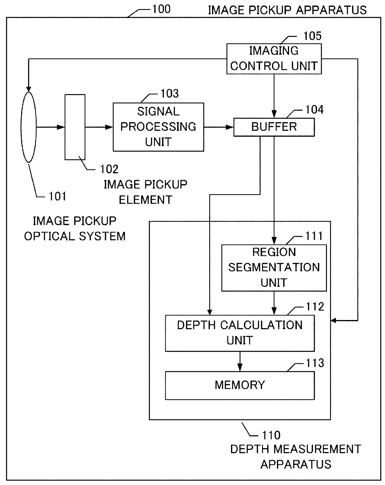
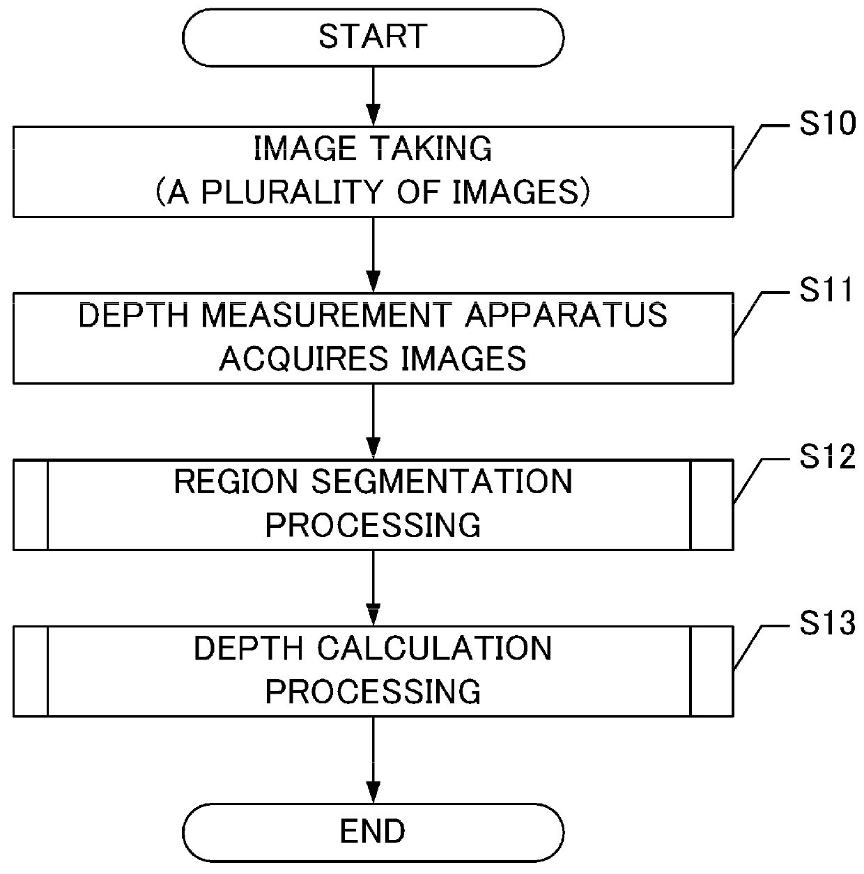
[0027]A first embodiment of the present invention is an image pickup apparatus 100 including a depth measurement apparatus 110. The depth measurement apparatus 110 is an apparatus that acquires a plurality of (e.g., two) images picked up by the image pickup apparatus 100 and calculates based on the images depth information on a subject at a plurality of positions in the image. Note that the depth information on the subject may be any information as long as the information is associated with the distance to the subject (depth distance). For example, a depth on an object side (a distance between the image pickup apparatus 100 and the subject, a distance between a focus position and the subject, or the like), a depth on an image surface side (a defocus amount or the like), or an index value (score) obtained by depth calculation according to a DFD method may al...

second embodiment

[0089]As shown in FIG. 6, the configuration of an image pickup apparatus according to the present embodiment is the same as that of the first embodiment, but the present embodiment is different from the first embodiment in the region segmentation method and the depth calculation method. Specifically, the operation of each of a region segmentation unit 211 and a depth calculation unit 212 is different.

[0090]Hereinbelow, the operation of each of the region segmentation unit 211 and the depth calculation unit 212 that is different from the operation in the first embodiment will be described in detail.

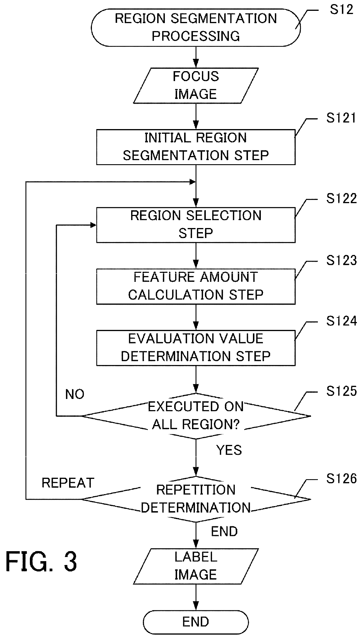
[0091]Unlike the first embodiment, the region segmentation unit 211 performs the region segmentation by using a plurality of taken images. In the present embodiment, a description will be given by using a case where two images are taken as an example. The flowchart of the region segmentation processing performed by the region segmentation unit 211 is shown in FIG. 7.

[0092]In each of an ini...

third embodiment

[0098]As shown in FIG. 8, the configuration of the present embodiment is substantially the same as the first and second embodiments, but is different from the first and second embodiments in that the imaging control is performed from a user interface (UI) and the region segmentation is performed by using the imaging parameter. Specifically, the present embodiment is different from the first and second embodiments in the addition of a UI 306 and the operation of a region segmentation unit 311.

[0099]Hereinbelow, the operation of the region segmentation unit 311 that is different from the operations of the first and second embodiments will be described in detail. Although the segmentation is performed such that the number of regions resulting from the segmentation (hereinbelow referred to as the segmentation number) predetermined based on the total number of pixels of the image pickup element is satisfied in the first and second embodiments, in the present embodiment, the segmentation ...


PUM


Abstract

A depth measurement apparatus calculates depth information on a subject in an image by using a plurality of images having different blurs taken under different imaging parameters, and includes a region segmentation unit that segments at least one of the images into regions based on an image feature amount, wherein in each of the regions pixels are presumed to be substantially equal in depth to the subject, and a depth calculation unit that calculates a depth for each region resulting from the segmentation by the region segmentation unit and serving as a processing target region for depth calculation, and sets the calculated depth as the depth of the processing target region.

Description

BACKGROUND OF THE INVENTION[0001]1. Field of the Invention[0002]The present invention relates to a technology for measuring depth information on a subject in an image by using image information.[0003]2. Description of the Related Art[0004]Conventionally, as a method for acquiring the depth of an imaging scene from an image acquired by an image pickup apparatus, a depth from defocus (DFD) method is proposed. In the DFD method, a plurality of images having different blurs are acquired by controlling imaging parameters of an image pickup optical system, and the correlation value of the mutual blurs is calculated on a per pixel basis in the plurality of images. In a case where only one pixel is used in depth calculation, the spread of the blur becomes obscure or the depth calculation becomes unstable due to a noise, and hence the correlation value is calculated with surrounding pixels included in the calculation. Finally, by using the relationship between the blur caused by the image pi...

Claims


Application Information

Patent Timeline
Patent Type & Authority Patents(United States)
IPC IPC(8): H04N13/02G06T7/00H04N13/00H04N13/221
CPCG06T7/0069G06T2207/10016H04N13/0221H04N13/0296H04N2013/0081G06T7/571H04N13/221H04N13/296
Inventor KOMATSU, SATORU
Owner CANON KK
Why Eureka
Try Eureka