System and method for image compression

a system and image compression technology, applied in the field of system and method for image compression and decompression, to achieve the effects of reducing difference or error, improving compression quality, and reducing compression quality

Active Publication Date: 2016-02-02
KALTURA INC
View PDF33 Cites 0 Cited by
  • Summary
  • Abstract
  • Description
  • Claims
  • Application Information

AI Technical Summary

Benefits of technology

[0009]There is an unmet need for, and it would be highly useful to have, a system and method for image compression that balances image quality (e.g., the accuracy of the compressed image data compared to the original image) and speed (e.g., the rate of data transmissions).
[0010]According to an embodiment of the invention, a system and method may dynamically alter the image quality (e.g., switching between lossy and lossless data, or varying degrees of data loss) depending on the available bandwidth or transmission rate, for example, increasing image quality when bandwidth increases and decreasing image quality when bandwidth decreases.
[0013]The maximum number of templates may be an adjustable parameter, dynamically set according to the system's available bandwidth or transmission rate. For example, embodiments of the invention may increase the maximum number of templates used to represent a sub-region (improving compression quality) when the available bandwidth or transmission rate increases, and may decrease the maximum number of templates used to represent the sub-region (reducing compression quality) when the available bandwidth or transmission rate decreases. Since each sequential template corrects for an incrementally diminishing error, the greater the number of templates / codes used to represent a sub-region, the generally more accurate is the compressed data for the sub-region.
[0014]Additionally, or alternatively, some embodiments of the invention may dynamically alter compressed image data quality by dynamically changing the dictionary or database size (e.g., defined by the number or variety of template patterns) depending on the available bandwidth. For example, embodiments of the invention may use a larger dictionary with longer template identifier codes, thereby improving quality when the available bandwidth increases, and may use a smaller dictionary with shorter template identifier codes, thereby lessening quality when the available bandwidth decreases.
[0015]Additionally or alternatively, some embodiments of the invention may dynamically alter compressed image data quality by dynamically changing the size, dimensions or resolution of the divided image sub-regions and their corresponding template patterns depending on the available bandwidth. For example, the size of the sub-regions and template pattern may be decreased, thereby improving the resolution and compression quality when available bandwidth increases, and may be increased, thereby lessening the resolution and compression quality when available bandwidth decreases.

Problems solved by technology

Lossy data may be used when the lost data is sufficiently small or when the benefit of data reduction outweighs the damages due to data loss.

Method used


Image

  • System and method for image compression
  • System and method for image compression
  • System and method for image compression

Examples


Embodiment Construction

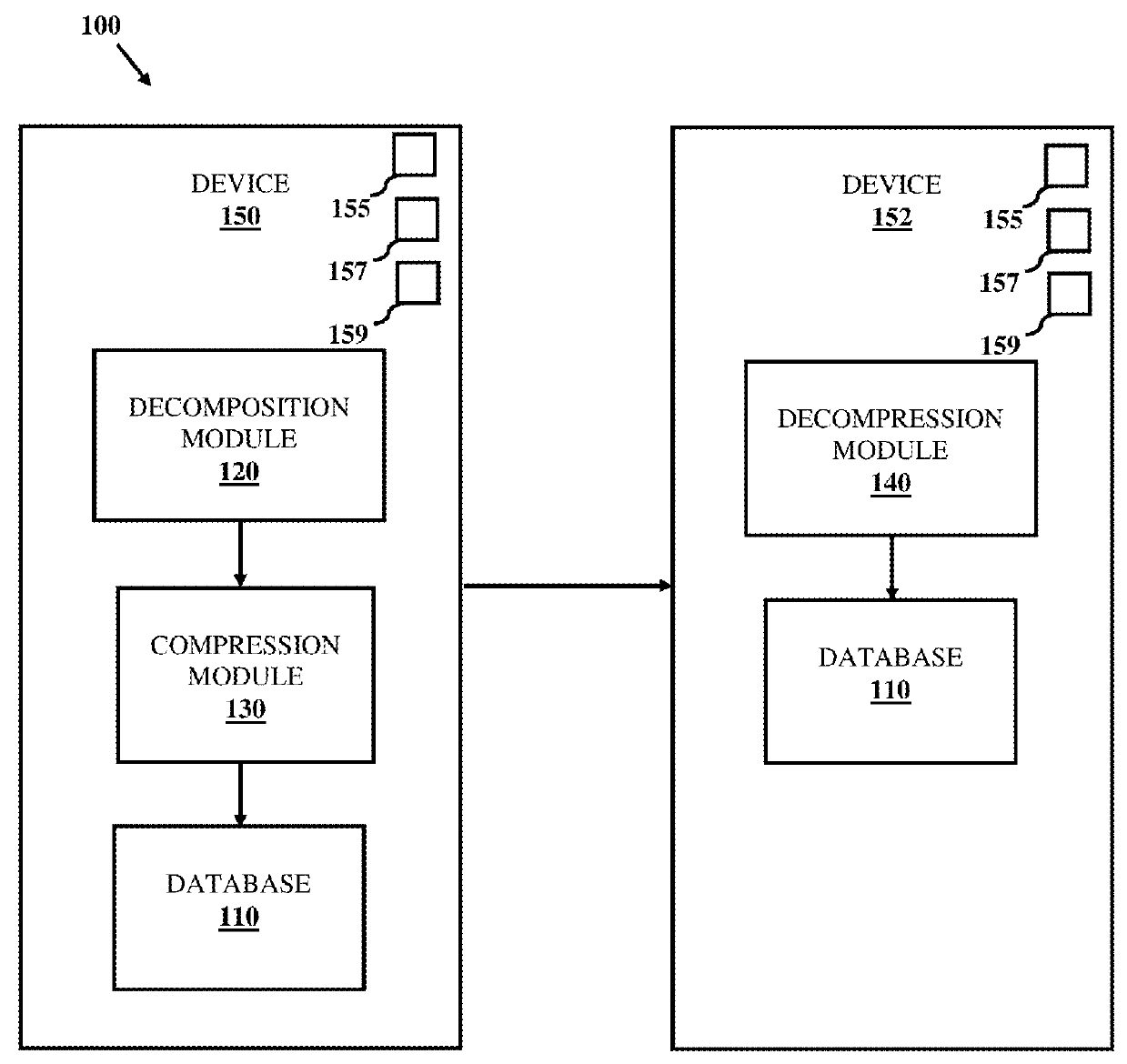
[0024]Some embodiments of the present invention provide a system and a method for dynamically adjusting the quality of image data compression based on the available bandwidth.

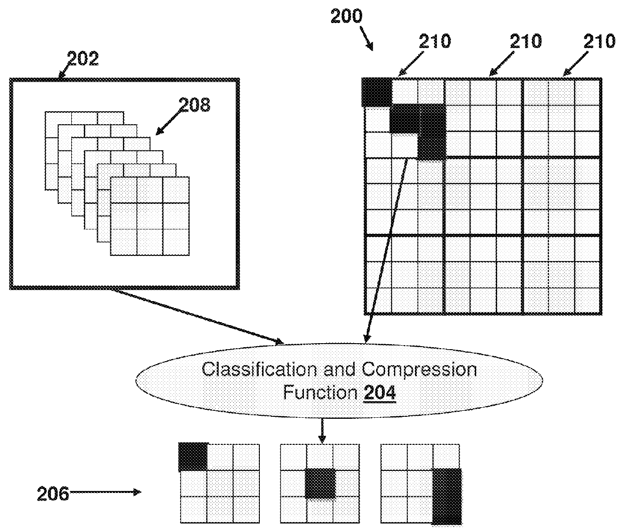
[0025]Some embodiments of the invention may divide a source image into a plurality of sub-regions and represent each source image sub-region by one or more similar template pattern(s) from among a dictionary or database of pre-existing image template pattern(s). The source image may represent an image itself, or a change or difference between an image and another previous or reference image. Each template pattern may be uniquely identified by an identifier, code or number. Sub-regions that remain constant with respect to the previous or reference image sub-region may be represented by no data or a “null” data indicator (e.g., 0).

[0026]In order for the image data to be compressed, the source image may be represented by a plurality or sequence of unique identifiers associated with the template patterns for the pl...


PUM


Abstract

A system and method for compressing digital image data. An image may be divided into sub-regions. A maximum number of template codes may be determined for representing each sub-region, each template code uniquely identifying a template pattern in a dictionary. Each of a plurality of the sub-regions may be associated with a plurality of template patterns, each of which individually does not match the sub-region, but which when combined together more closely match the sub-region. A compressed data set may be generated for the image, in which each sub-region is represented by up to the maximum number of template codes uniquely identifying the associated plurality of template patterns. The up to the maximum number of template codes may be transmitted for each sub-region from the compressed data set, wherein the maximum number of template codes is a dynamic parameter adjustable based on the bandwidth available for transmitting.

Description

CROSS-REFERENCE TO RELATED APPLICATIONS[0001]This application is a continuation-in-part of U.S. patent application Ser. No. 13 / 259,877, filed Sep. 23, 2011, now U.S. Pat. No. 8,774,534 which is a national phase of International Patent Application Ser. No. PCT / US10 / 30425, which in turn claims the benefit of U.S. Provisional Patent Application Ser. No. 61 / 167,536 filed Apr. 8, 2009, all of which are incorporated by reference herein in their entirety.FIELD OF THE INVENTION[0002]The present invention relates to systems and methods for image compression and decompression, and in particular for reducing the amount of data used to represent images.BACKGROUND OF THE INVENTION[0003]Digital imaging may create digital images, typically from a physical object. A digital image may be created directly from a physical scene by a camera or similar devices. Alternatively, a digital image may be obtained from another image in an analog medium, such as photographs, photographic film or printed paper, ...

Claims


Application Information

Patent Timeline
Patent Type & Authority Patents(United States)
IPC IPC(8): G06K9/36H04N19/593H04N19/46H04N19/90
CPCH04N19/593H04N19/46H04N19/90
Inventor ZAROM, RONY
Owner KALTURA INC
Why Eureka
Try Eureka