Fiber optic cable for distributed acoustic sensing with increased acoustic sensitivity

a fiber optic cable and distributed acoustic technology, applied in glass optical fibre, survey, borehole/well accessories, etc., can solve the problem of creating very small strain changes in optical fibers

Active Publication Date: 2016-02-09
WEATHERFORD TECH HLDG LLC
View PDF28 Cites 31 Cited by
  • Summary
  • Abstract
  • Description
  • Claims
  • Application Information

AI Technical Summary

Problems solved by technology

Externally generated acoustic disturbances may create very small strain changes to optical fibers.

Method used


Image

  • Fiber optic cable for distributed acoustic sensing with increased acoustic sensitivity
  • Fiber optic cable for distributed acoustic sensing with increased acoustic sensitivity
  • Fiber optic cable for distributed acoustic sensing with increased acoustic sensitivity

Examples


Embodiment Construction

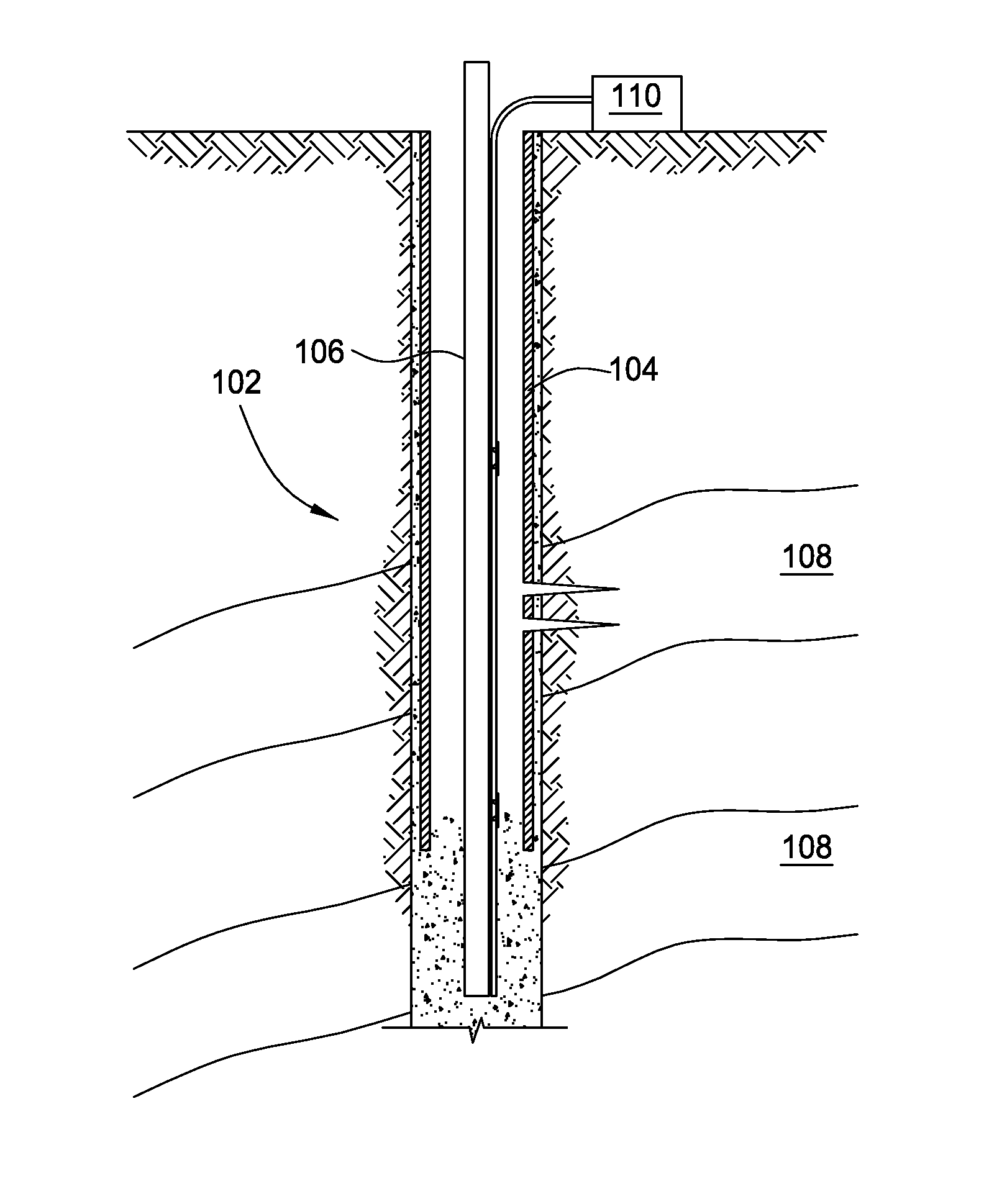
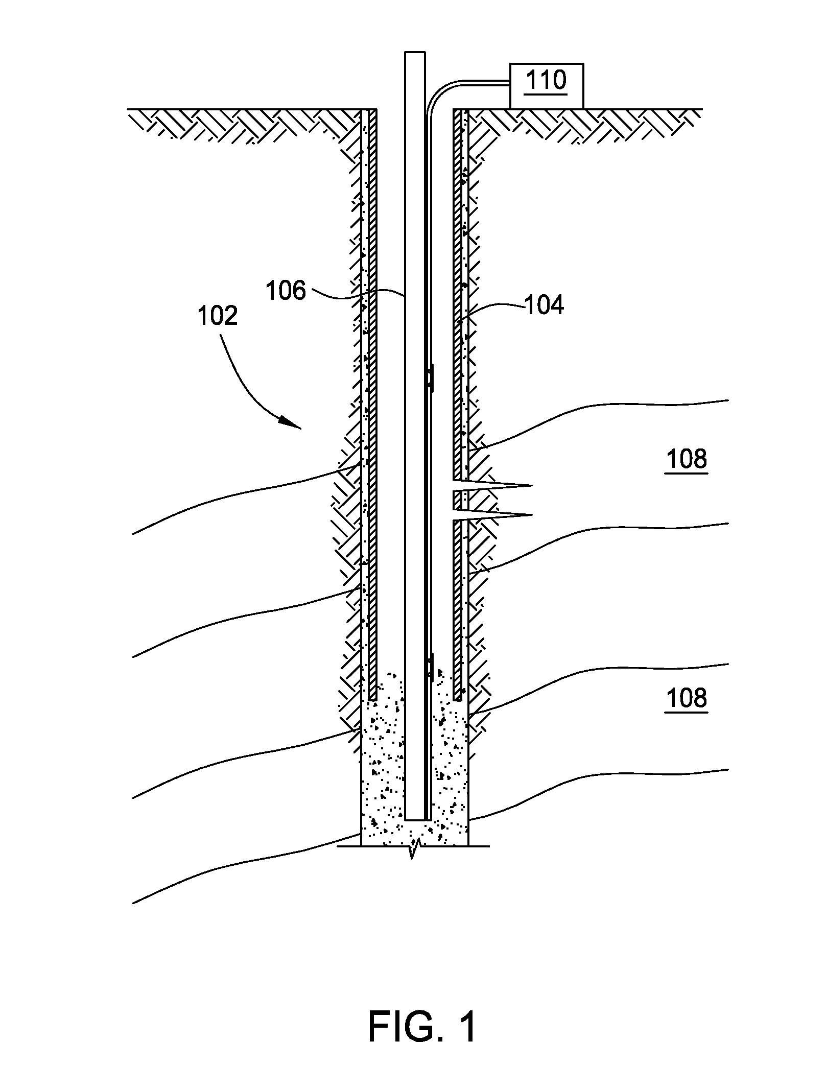
[0024]Embodiments of the present invention provide methods and apparatus for performing Distributed Acoustic Sensing (DAS) using fiber optics with increased acoustic sensitivity. Acoustic sensing of a wellbore, pipeline, or other conduit / tube based on DAS may have increased acoustic sensitivity through fiber optic cable design, increasing the Rayleigh backscatter property of a fiber's optical core, and / or using inclusions or attachments to the cable or fiber.

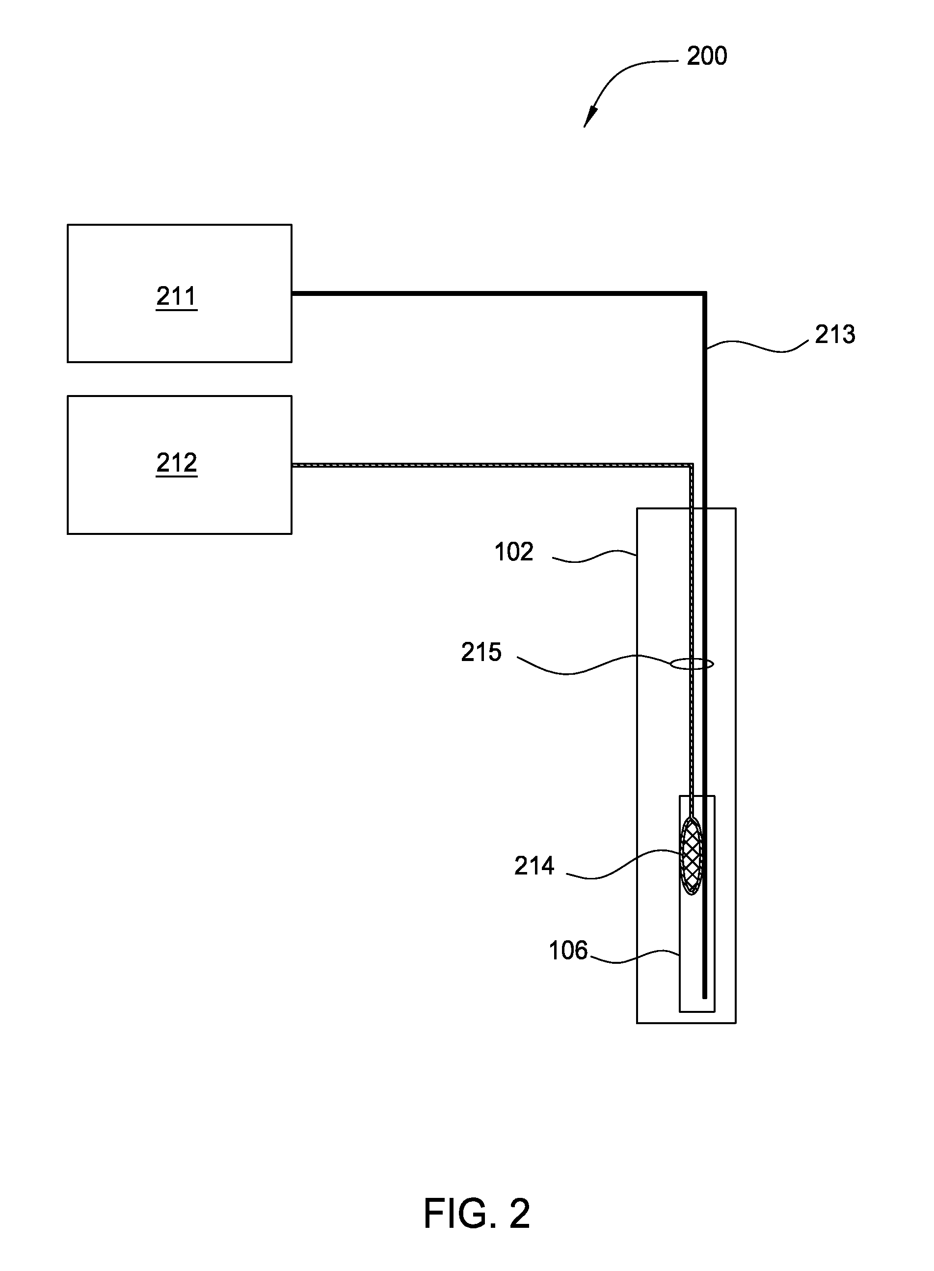
[0025]FIG. 2 illustrates an embodiment of a DAS system 200, comprising an acoustic energy source 214 and a DAS device 213 both embedded within a cable 215 inside the wellbore 102, such as within the production tubing 106, as shown. For some embodiments, a portion of the DAS system 200 may be permanently emplaced for sonic well logging. The acoustic energy source 214 may be controlled by an acoustic energy source controller 212, typically disposed at the surface. For example, the controller 212 may transmit electrical pulses in a...


PUM


Abstract

Methods and apparatus for performing Distributed Acoustic Sensing (DAS) using fiber optics with increased acoustic sensitivity are provided. Acoustic sensing of a wellbore, pipeline, or other conduit / tube based on DAS may have increased acoustic sensitivity through fiber optic cable design and / or increasing the Rayleigh backscatter property of a fiber's optical core. Some embodiments may utilize a resonant sensor mechanism with a high Q coupled to the DAS device for increased acoustic sensitivity.

Description

CROSS-REFERENCE TO RELATED APPLICATIONS[0001]This application is a continuation of U.S. patent application Ser. No. 13 / 163,323, filed on Jun. 17, 2011 now abandoned, which claims benefit of U.S. Provisional Patent Application Ser. No. 61 / 355,924, filed Jun. 17, 2010, both of which are herein incorporated by reference.BACKGROUND OF THE INVENTION[0002]1. Field of the Invention[0003]Embodiments of the present invention generally relate to methods and apparatus for performing acoustic sensing based on Distributed Acoustic Sensing (DAS) with increased acoustic sensitivity.[0004]2. Description of the Related Art[0005]Sensing of a wellbore, pipeline, or other conduit / tube (e.g., based on acoustic sensing) may be used to measure many important properties and conditions. For example, formation properties that may be important in producing or storing fluids in downhole reservoirs comprise pressure, temperature, porosity, permeability, density, mineral content, electrical conductivity, and bed...

Claims


Application Information

Patent Timeline
Patent Type & Authority Patents(United States)
IPC IPC(8): E21B49/00G02B6/00G01H9/00E21B47/12
CPCG01H9/004E21B47/123G01V2210/1429E21B47/135G02B6/02342G02B6/02395G02B6/4433
Inventor TAVERNER, DOMINOGRUNBECK, JOHN J.DUNPHY, JAMES R.DOWD, EDWARD M.KUCZMA, ANDREW S.BOSTICK, III, FRANCIS X.LABELLA, DAVIDBAKER, MARK
Owner WEATHERFORD TECH HLDG LLC
Why Eureka
Try Eureka