Sounding reference signal transmission in carrier aggregation

a reference signal and carrier technology, applied in power management, high-level techniques, wireless commuication services, etc., to achieve the effect of increasing uplink spectral efficiency, efficient power utilization method, and reducing or puncturing power

Active Publication Date: 2016-02-09
RES IN MOTION LTD
View PDF17 Cites 14 Cited by
  • Summary
  • Abstract
  • Description
  • Claims
  • Application Information

AI Technical Summary

Benefits of technology

[0021]In accordance with an aspect of the present invention, a cell-specific sounding reference symbol (SRS) subframe configuration and UE-specific SRS configuration are defined for carrier aggregation. For the cell-specific SRS subframe configuration, in one embodiment, the same cell-specific SRS subframes are configured for all uplink (UL) carrier components (CCs). In another embodiment, different UL CCs may be configured with different cell-specific SRS subframe configurations. For the UE-specific SRS configuration, different configurations may be applied for different UL CCs allocated to the UE. Also, to reduce signaling overhead, the different UE-specific SRS configuration is signaled by using an offset or delta on top of the UE-specific SRS configuration of one of the CCs allocated to the UE, such as the primary component carrier (PCC).
[0024]Such a system allows configuration of multiple SRSs. More specifically, the eNB configures the same or different cell-specific SRS subframes for different CC and for each UE, different UE-specific SRS configuration for different CC may be configured. It is beneficial to avoid a Peak to Average Power Ratio (PAPR) issue caused by multiple SRSs transmission while reducing the puncturing of PUSCH or PUCCH due to the cell specific SRS subframes. An additional advantage is that the signaling methods reduce the signaling overhead.
[0026]With the power control for SRS transmission in power limited situation, when SRS and other uplink channels are simultaneously transmitted, this method defines how to transmit multiple channels in case of the power limited situation. The method provides an efficient power utilization method because it reduces or punctures the power based on channel priority. Therefore, the method increases uplink spectral efficiency.

Problems solved by technology

However, out of band emissions are still of concern with the multi channel transmission.
Another remaining issue is when SRS and other uplink channels are transmitted simultaneously in different CCs.
If simultaneous transmission of SRS and other uplink channels is allowed, an issue is present relating to how to scale the power of each channel when the calculated total transmit power exceeds the maximum allowed transmit power, i.e., a power-limited situation.

Method used


Image

  • Sounding reference signal transmission in carrier aggregation
  • Sounding reference signal transmission in carrier aggregation
  • Sounding reference signal transmission in carrier aggregation

Examples


Embodiment Construction

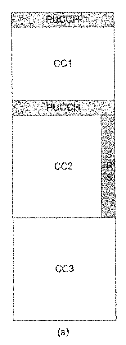
[0042]Referring to FIGS. 6A and 6B, generally referred to as FIG. 6, block diagrams of examples of configuration of cell specific SRS subframes are shown. More specifically, a method to reduce the overhead of signaling SRS subframes in carrier aggregation is set forth. Although it is desirable for a UE to transmit SRS for different UL CCs in different subframes to avoid a peak to average power ratio (PAPR) issue, there is benefit to assigning the same cell-specific SRS subframes between different UL CCs. As shown in FIG. 6A, uplink subframes are expected to be time-aligned between different UL CCs, since all UL CCs belong to the same eNB. FIG. 6A shows an example when cell-specific SRS subframes are aligned among multiple CCs, while FIG. 6B shows an example of when the cell-specific SRS subframes are different in multiple CCs.

[0043]In FIG. 6A, within the cell specific SRS subframe, certain areas (e.g., the first parts of UL CC1 subframe 1, 3 and 5 and all of UL CC1 subframe 2 and 4)...


PUM


Abstract

A cell-specific sounding reference symbol (SRS) subframe configuration and UE-specific SRS configuration are defined for carrier aggregation. For the cell-specific SRS subframe configuration, the same cell-specific SRS subframes are configured for all uplink (UL) carrier components (CCs). For the UE-specific SRS configuration, different configurations are applied for UL CCs. Also, to reduce signaling overhead, the different UE-specific SRS configuration is signaled by using an offset on top of the UE-specific SRS configuration of a primary component carrier (PCC).

Description

CROSS REFERENCE TO RELATED APPLICATIONS[0001]This application is a continuation of PCT / US2010 / 049408 filed on Sep. 17, 2010. The entire contents of the PCT international application are incorporated herein by reference.BACKGROUND OF THE INVENTION[0002]1. Field of the Invention[0003]The present invention generally relates to data transmission in mobile communications systems and more particularly to sounding reference signal (SRS) transmission in carrier aggregation.[0004]2. Description of the Related Art[0005]In known wireless telecommunications systems, transmission equipment in a base station or access device transmits signals throughout a geographical region known as a cell. As technology has evolved, more advanced equipment has been introduced that can provide services that were not possible previously. This advanced equipment might include, for example, an E-UTRAN (evolved universal terrestrial radio access network) node B (eNB), a base station or other systems and devices. Suc...

Claims


Application Information

Patent Timeline
Patent Type & Authority Patents(United States)
IPC IPC(8): H04L5/00H04W28/06
CPCH04L5/0048H04L5/001H04L5/0066H04L5/0078H04L5/0096H04W28/06Y02D30/70H04W72/21H04W52/367
Inventor HEO, YOUN HYOUNGFONG, MO-HANBUCKLEY, MICHAEL EOINEARNSHAW, MARKCAI, ZHIJUN
Owner RES IN MOTION LTD
Why Eureka
Try Eureka