Window security device

a window security and window lock technology, applied in the direction of building locks, construction fastening devices, construction, etc., can solve the problems of easy home burglaries, and achieve the effect of easy installation and easy removal

Inactive Publication Date: 2016-02-16
JEWETT RICHARD H
View PDF24 Cites 5 Cited by
  • Summary
  • Abstract
  • Description
  • Claims
  • Application Information

AI Technical Summary

Benefits of technology

[0011]This invention provides a universal device to secure a window that is customizable, can be used in many different window sizes, and can be easily removed and used in a different window. It is used to secure a window so that it cannot be opened for the prevention of unwanted intruders into a home, business or other type of building. In particular, the invention prevents forced entry through single or double hung sash-type windows.
[0012]The invention is a window jamming device designed to stay positioned in place to prevent the forced opening and entry of a window. To minimize shipping costs, the inventive device may be offered as a “do-it-yourself” kit with the customer providing the upper portion in the suitable length of ½″ PVC S-40 pipe for windows (vertical installation), or ½″ iron pipe for sliding doors (horizontal installation). A customized length upper portion also provides customers the opportunity to increase or decrease the degree of spring compression desired.
[0014]The present invention will block or jam these types of forced entries and intrusions. It is easy to install, easy to remove, easy to re-install, and easy to reconfigure for different windows in different locations. The inventive window security device will not damage window frames and is adaptable to any type of window frame material such as wood, vinyl, or aluminum.
[0016]Nearly any two surfaces which are parallel to each other and include flat facing surfaces could potentially be made resistant to opening forces by the present invention. The present invention when placed along the side portion of the window frame will be unobtrusive and easily disguised with curtains or blinds. It is a security device that could be provided by landlord and renter alike due to low cost and ease of installation. The device of the present invention is easily removed by an occupant of a building needing to open the window quickly, such as in the case of a fire emergency.
[0033]A further object or feature of the present invention is a new and improved window security device that is easy to install.
[0034]An even further object of the present invention is to provide a novel window security device that is easily removed when necessary.

Problems solved by technology

Unfortunately, home burglaries are made easy when all the thief needs is a pry-bar to gain entry by forcing up the lower sash window.

Method used


Image

  • Window security device
  • Window security device
  • Window security device

Examples


Embodiment Construction

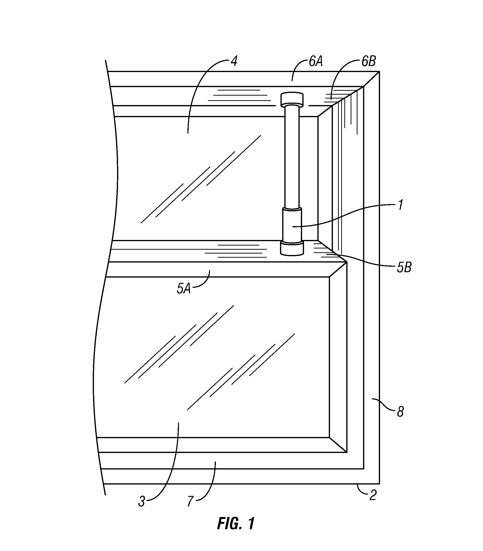
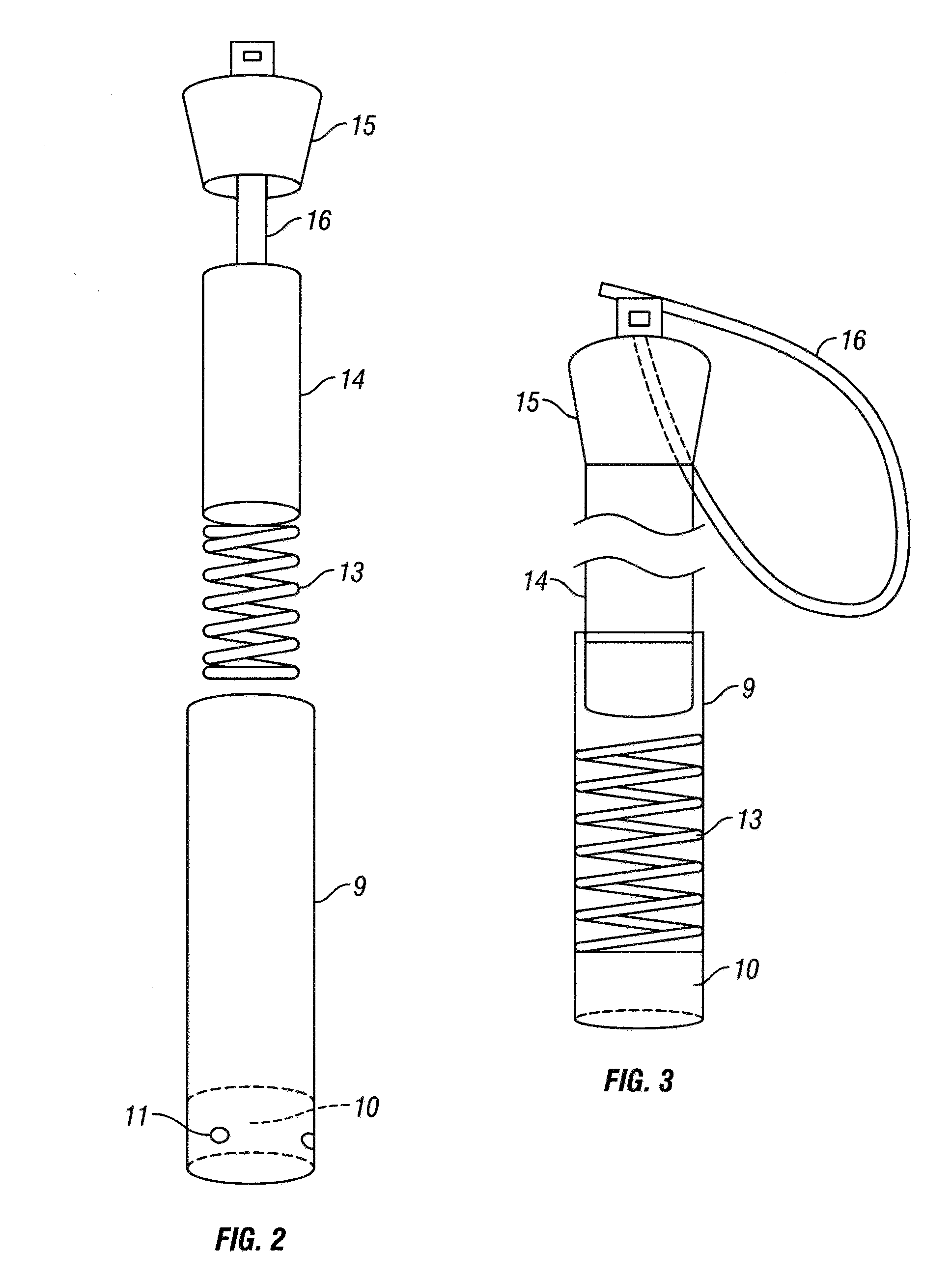
[0045]Referring to FIGS. 1 through 4B, wherein like reference numerals refer to like components in the various views, there is illustrated therein a new and improved window security device, generally denominated 1 herein.

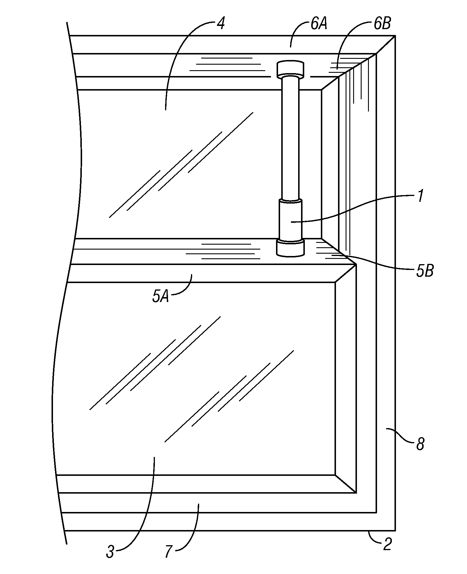
[0046]FIG. 1 shows the window security device 1 of this invention positioned in place in a typical sash type window 2 with window frame sill 7 and window frame head 6A. The lower sash window 3 has an upper surface 5B of center meeting rail 5A which runs horizontally and planar to the lower surface 6B of the window frame head 6A of the window frame 8.

[0047]The upper portion of the window security device 1 is in contact with the lower surface 6B of the window frame head 6A of the window frame 8, while the bottom portion of the window security device 1 is in contact with the upper surface 5B of the meeting rail 5A of the lower sash window 3. In this example, the lower sash window 3 is movable up and down within the window frame 2, but is prevented from opening by insta...


PUM


Abstract

A removable window security device includes a base unit with a silicone plug and an internal compression spring, which supports a custom-length upper portion capped with a non-slip rubber cap. The silicone plug serves as a pad for the compression spring and a non-slip bottom for the base unit. The assembled device is positioned in the window between the sashes, preventing the window from being opened.

Description

CROSS REFERENCE TO RELATED APPLICATIONS[0001]Not applicable.STATEMENT REGARDING FEDERALLY SPONSORED RESEARCH OR DEVELOPMENT[0002]Not applicable.REFERENCE TO A MICROFICHE APPENDIX[0003]Not applicable.TECHNICAL FIELD[0004]The present invention relates generally to home security devices, and more specifically to a window security device of the type that may be used for the protection of residential windows against intruders using a pry-bar.BACKGROUND INFORMATION AND DISCUSSION OF RELATED ART[0005]Homes can be burglarized by prying open a window that is locked, including windows with a thumbscrew security device securely attached. Some homeowners attempt to secure a window by fitting a 1″ by 2″ stick or other brace in such a way that it would prevent the window from being “jimmied” open or the prop falling out or being dislodged. This is a poor solution in addition to being dangerous in case of fire. There are other window security products that are designed to be an adjustable prop, bu...

Claims


Application Information

Patent Timeline
Patent Type & Authority Patents(United States)
IPC IPC(8): E05C19/18E05C17/44E05C17/54E05B65/08
CPCE05C17/44E05C17/54E05B65/0888E05B65/0894E05C2007/007
Inventor JEWETT, RICHARD, H.
Owner JEWETT RICHARD H
Why Eureka
Try Eureka