

Modular ball drop
a module and ball drop technology, applied in mechanical equipment, sealing/packing, wellbore/well accessories, etc., can solve the problems of inability to simultaneously drop/inject multiple balls of the same diameter, poor adaptability to the effect of ball drop, and more fragile small frac balls
- Summary
- Abstract
- Description
- Claims
- Application Information
AI Technical Summary
Benefits of technology
Problems solved by technology
Method used
Image

Examples
Embodiment Construction
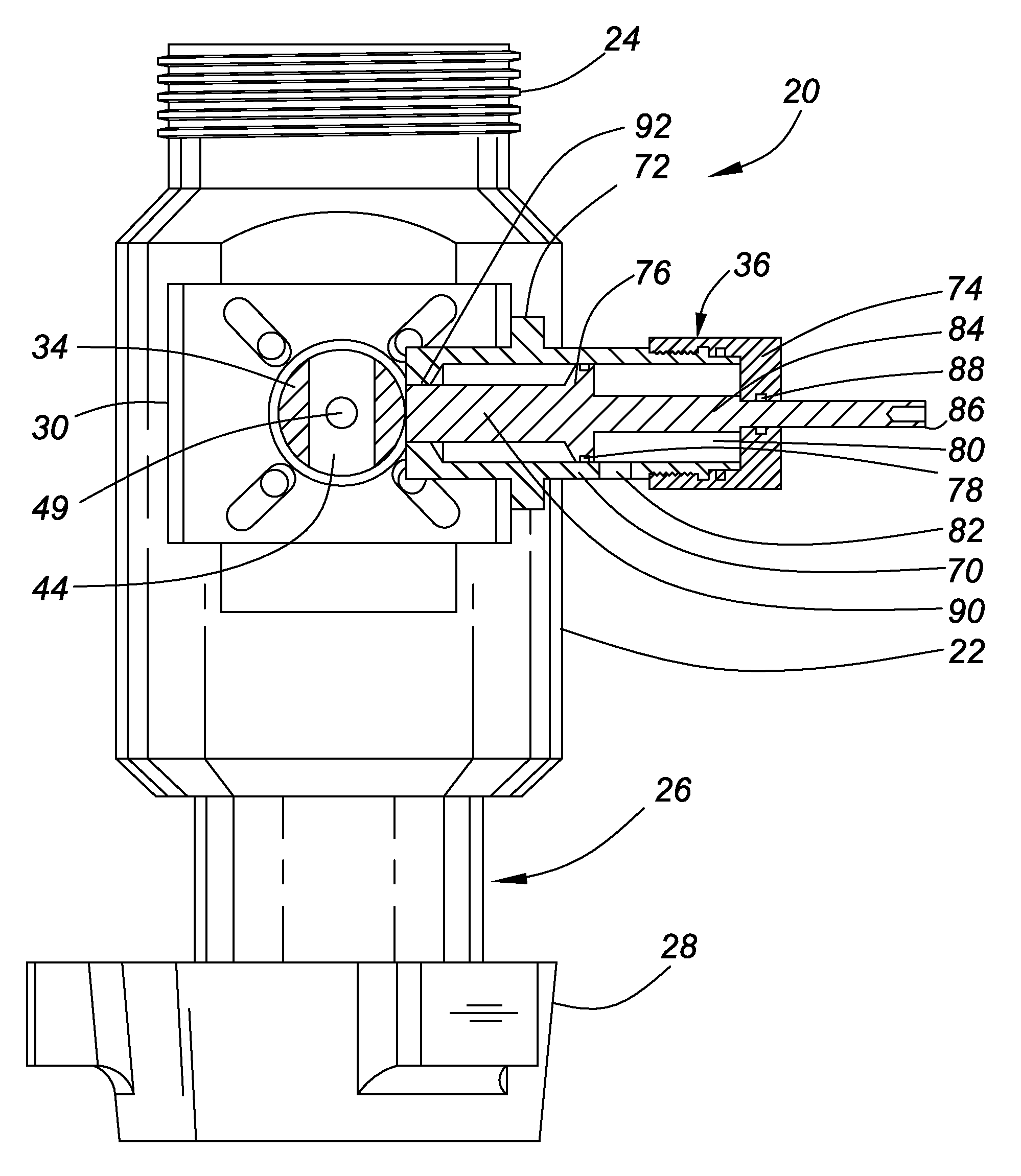
[0022]The invention provides a modular ball drop that permits a group of frac balls of the same diameter to be simultaneously injected into a well. Any required number of ball drop modules can be vertically stacked to permit a required number of groups of frac balls to be sequentially injected into the well. The modular ball drop may also be used to inject only one ball at a time, or any combination of single and / or multiple balls, into the well. A positive lock engages when a module is moved from the ball retention to the ball released position to prevent obstruction of subsequent ball drops from the modular ball drop.
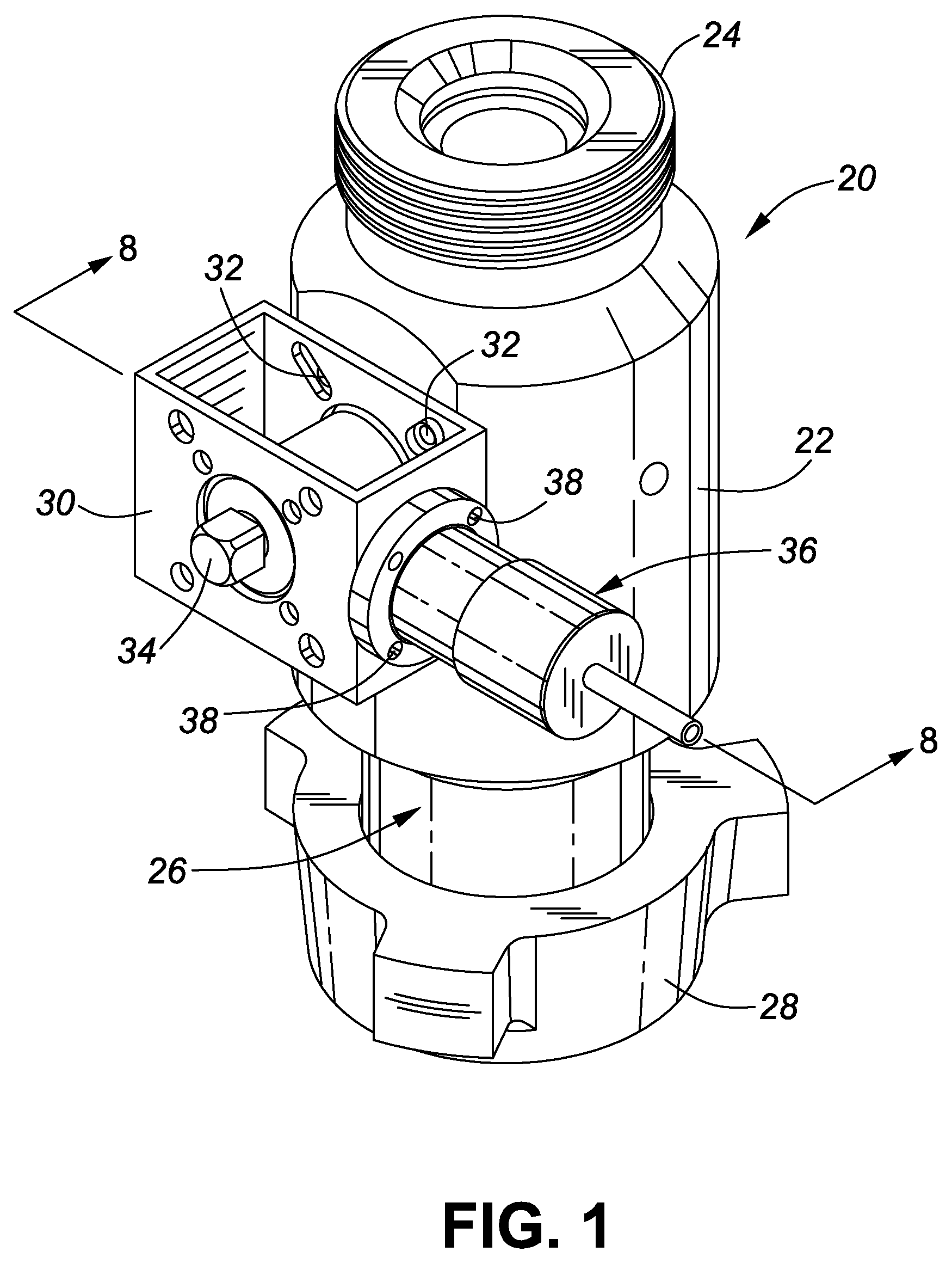
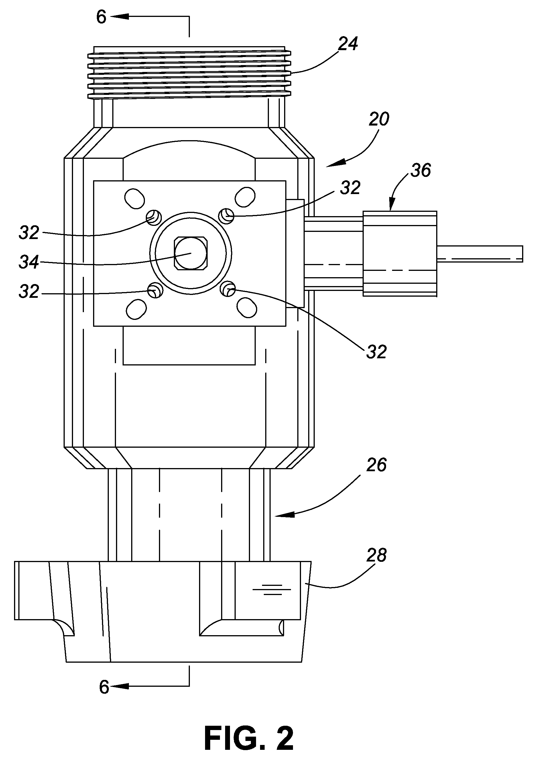
[0023]FIG. 1 is an isometric view of one embodiment of a ball drop module 20 in accordance with the invention. The ball drop module 20, hereinafter referred to as module 20, includes a tubular body 22. This embodiment of the module 20 is provisioned with quick-disconnect threaded unions described in assignee's U.S. Pat. No. 7,484,776 which issued Feb. 3, 2009, the spe...
PUM
 Abstract
Description
Claims
Application Information