Hydroelectric power generating system

a technology of hydroelectric power generation and power generation system, which is applied in the direction of water-power plants, electric generator control, machines/engines, etc., can solve problems such as net loss of energy, and achieve the effect of reducing sea level and “clean” energy

Active Publication Date: 2016-02-16
BARAKAT YASER K
View PDF34 Cites 16 Cited by
  • Summary
  • Abstract
  • Description
  • Claims
  • Application Information

AI Technical Summary

Problems solved by technology

While this system results in a net loss of energy, it does enable the reservoir to be replenished during periods where surplus electrical energy is available.

Method used


Image

  • Hydroelectric power generating system
  • Hydroelectric power generating system
  • Hydroelectric power generating system

Examples


Embodiment Construction

[0020]The hydroelectric power generating system greatly expands upon the availability of conventional hydroelectric power systems, using a relatively small man-made dam extending across a natural channel to form a reservoir enclosed by natural terrain. While such facilities are quite valuable for the power they produce, as well as for their recreational and flood control benefits, the number of such facilities is limited by the lack of availability of natural terrain permitting their construction and efficient operation.

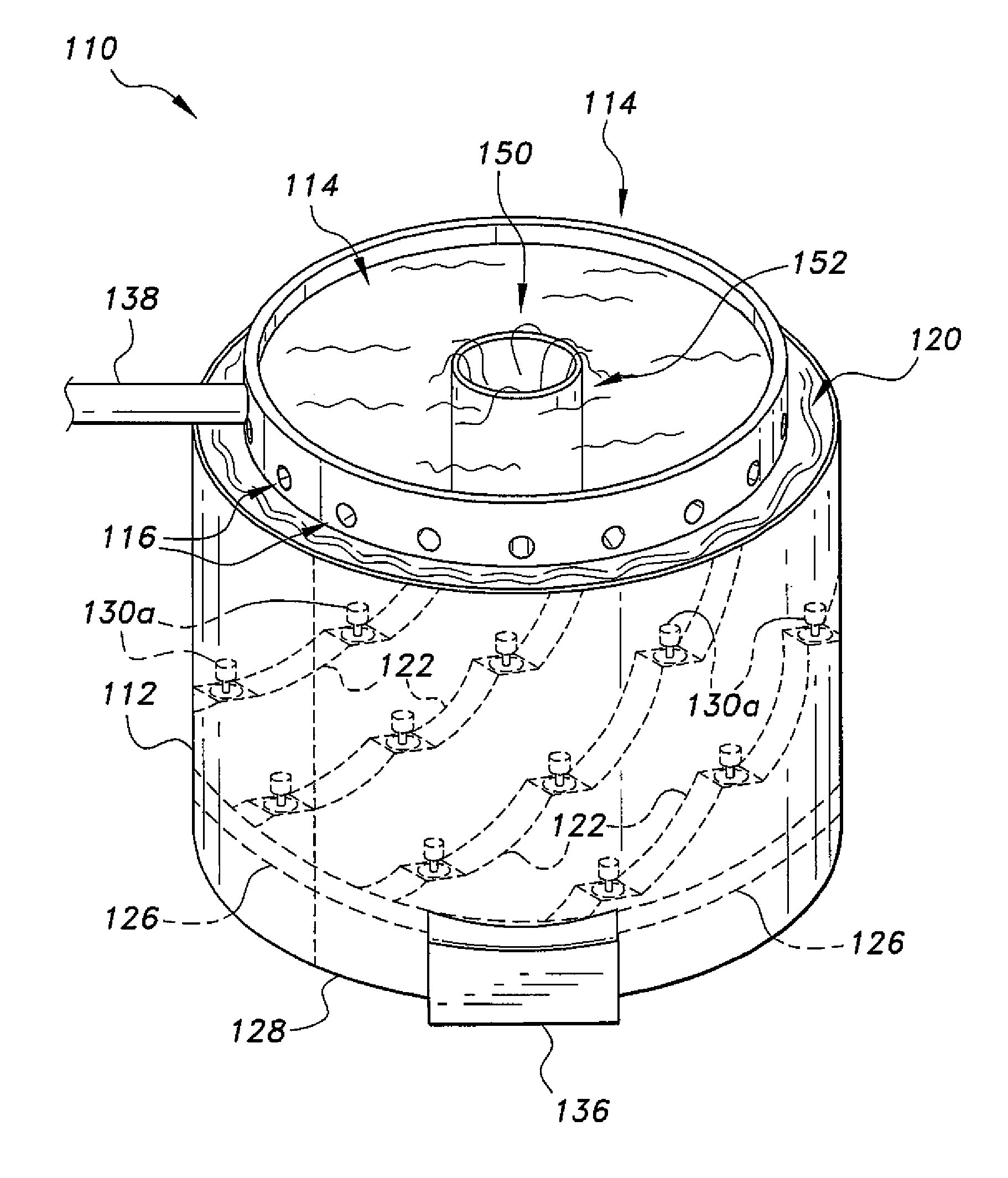
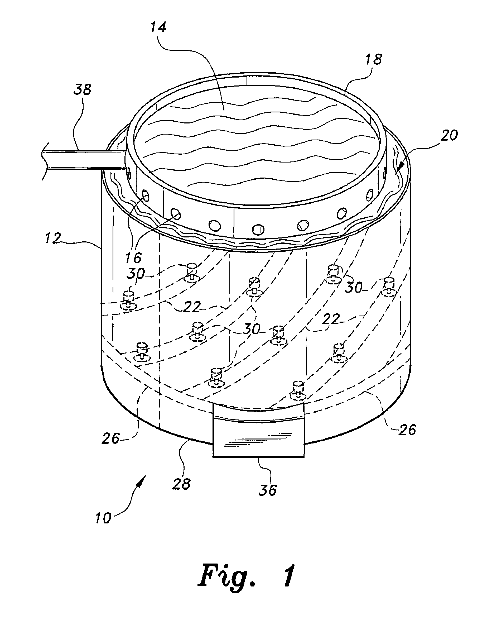
[0021]FIG. 1 of the drawings provides a diagrammatic perspective view of an exemplary hydroelectric power generating system 10 according to the present invention. The system 10 incorporates a relatively large dam 12 or wall defining a dam that completely encircles or laterally encloses a reservoir 14 therein. The dam 12 may have a generally cylindrical configuration, as shown in FIG. 1, or may have any other desired external shape or configuration. The dam 12 include...


PUM


Abstract

The hydroelectric power generating system incorporates a man-made dam structure configured to completely enclose a body of water. The dam is preferably filled by pumping seawater into the reservoir defined by the encircling dam. A circumferential canal feeds water to one or more penstocks. Each penstock has one or more hydroelectric turbine generators installed therealong. The penstocks feed an enclosed circumferential channel about the base of the dam. The channel delivers water to a pump that pumps the water back into the bottom of the reservoir. An auxiliary hydroelectric power generating system disposed within the dam utilizes the water exiting from the lower end of the penstocks for additional production of energy. While this system results in a net loss of energy, the system can make use of surplus power to drive the return pump during periods of low electrical demand in order to replenish the reservoir.

Description

CROSS-REFERENCE TO RELATED APPLICATIONS[0001]This is a continuation-in-part of my presently pending U.S. Non-Provisional patent application Ser. No. 14 / 156,408, filed on Jan. 15, 2014, which claims the benefit of my U.S. Provisional Patent Application Ser. No. 61 / 753,302, filed Jan. 16, 2013.BACKGROUND OF THE INVENTION[0002]1. Field of the Invention[0003]The present invention relates to electrical power generating systems, and particularly to a hydroelectric power generating system incorporating man-made reservoirs that each have one or more penstocks extending from a common waterway and one or more electrical generating turbines disposed along each of the penstocks.[0004]2. Description of the Related Art[0005]Hydroelectric power generating systems have been known for a considerable period of time. Conventional systems utilize a natural geographic basin, valley, or the like, and place a man-made dam across a channel in the natural terrain to create a reservoir upstream of the dam. T...

Claims


Application Information

Patent Timeline
Patent Type & Authority Patents(United States)
IPC IPC(8): F03B13/00H02P9/04F03B13/10F03B13/12E02B13/00E02B9/00E02B7/40E02B3/10E02B7/02F03B13/06
CPCF03B13/00F03B13/06Y02E10/22Y02E60/17Y02E10/20Y02E60/16
Inventor BARAKAT, YASER, K.
Owner BARAKAT YASER K
Why Eureka
Try Eureka