
Performance estimation method and scale-up method for particle size breakup apparatus of a rotor-stator type

a technology of particle size breakup and performance estimation, which is applied in the direction of adaptive control, instruments, force/torque/work measurement apparatus, etc., can solve the problems of not being able to apply indices to the mixers of the various types having the different configurations, and not being able to use estimation methods

Active Publication Date: 2016-02-16
MEIJI CO LTD
View PDF43 Cites 0 Cited by
  • Summary
  • Abstract
  • Description
  • Claims
  • Application Information

AI Technical Summary

Benefits of technology

This patent is about a new method for estimating the performance of different types of mixers used in industries like food, pharmaceuticals, and chemicals. The method takes into account factors like the gap between the rotor and stator, or the type of circulation system used. The method allows for the estimation of the time it takes for the mixer to run, and the size of the particles produced during that time. This information can then be used to manufacture products with the desired particle size. Overall, the method improves the efficiency and accuracy of the mixing process.

Problems solved by technology

In most cases, however, those indices can only be applied to each individual mixer having the same configuration.
In the actual cases, however, they cannot be applied to the mixers of the various types having the different configurations.
There are also no study cases in which those methods can be applied to the mixers of the various types having the different configurations, and the data on the results obtained by the experiments on such study cases have not been arranged or organized into the graphical chart.
More specifically, in the prior art, there is no estimation method that can be used to estimate the drop diameters that would be obtained by using the large-scale devices (actual production installation) for the mixers of the various types and permitting such large-scale devices to run during the particular time period, or there is no estimation method that can be used to estimate the particular drop diameters obtained during the particular running time or during the processing (agitating) time required until such particular drop diameters can be obtained.

Method used


Image

  • Performance estimation method and scale-up method for particle size breakup apparatus of a rotor-stator type
  • Performance estimation method and scale-up method for particle size breakup apparatus of a rotor-stator type
  • Performance estimation method and scale-up method for particle size breakup apparatus of a rotor-stator type

Examples


embodiment 1

[0186]A liquid that is provided for simulating a dairy product is prepared as an object of estimating its particle size breakup. This liquid that simulates the dairy product contains the milk protein concentration (MPC, TMP (total milk protein)), rapeseed oil, and water. Its composition and ratio are presented in Table 1.

[0187]

TABLE 1Composition Ratio of Simulated Liquid for Milk ProductCompositionMilk Product Concentrate (MPC) 8.0%Rape Seed Oil 4.5%Water87.5%Total. 100%RatioProtein / Water 9.1%Oil / Protein56.3%Oil / Water 5.1%PropertiesDensity1028 kg / m3Viscosity 15 mPa · s

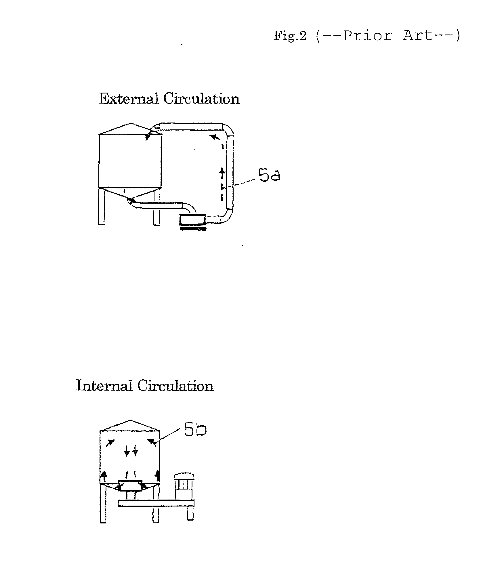
[0188]The mixer performance was estimated by checking the particle size breakup trend for the drop diameters on the experimental basis. The unit that employs the external circulation system as shown in FIG. 3 was provided, and the drop diameters were measured on the middle way of the fluid or liquid path by using the laser diffraction-type particle size analyzer (SALD-2000 as offered by Shimazu Manufacturing Company).

[...

embodiment 2

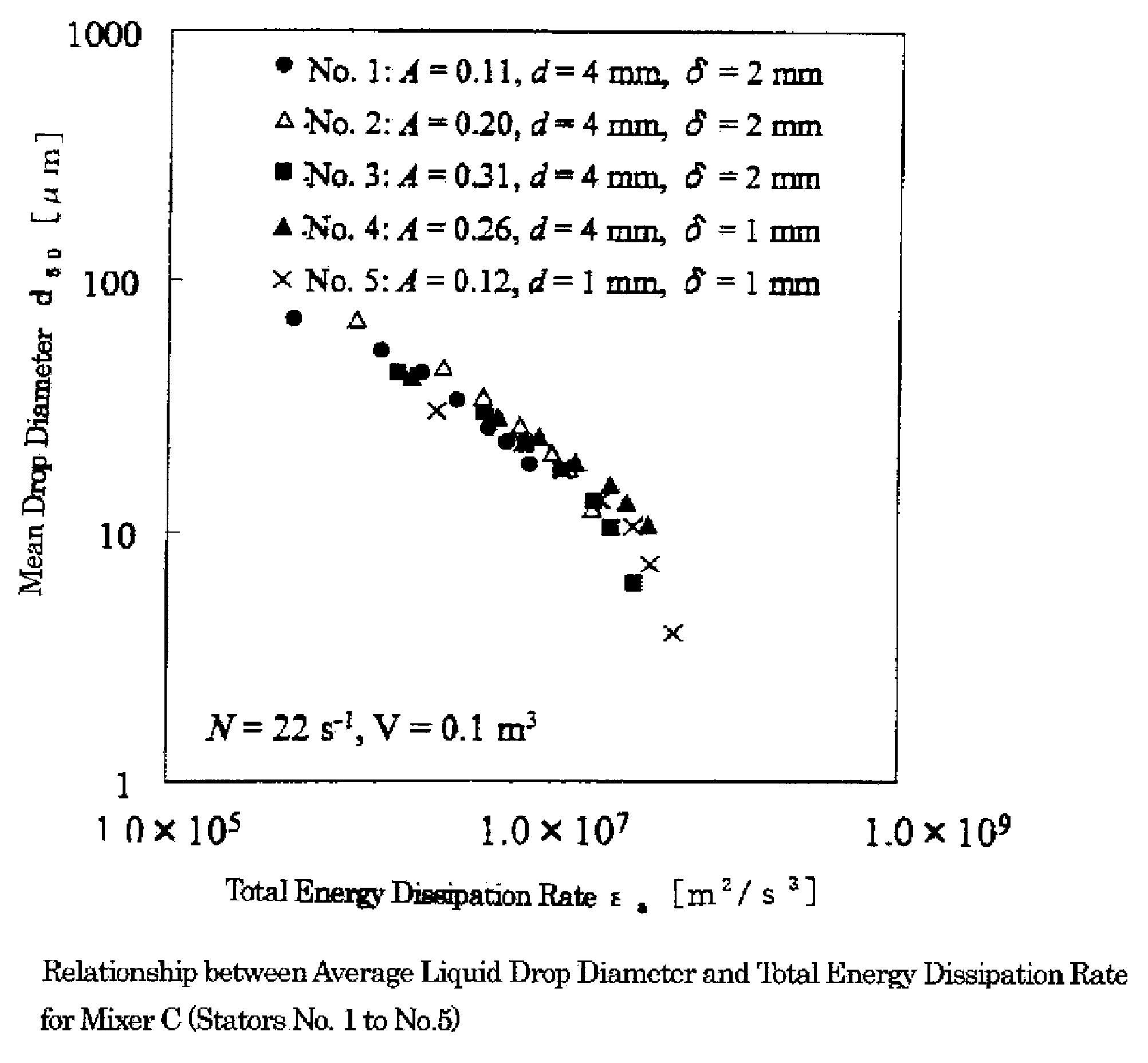
[0209]In this embodiment, the performance was compared for the three mixers in which the gap δ between the rotor 3 and stator 2 is large (δ>1 mm, e.g. δ=2 to 10 mm), for example, and the number of openings (holes) 1 for the stator 2 is large (ns>20, e.g. ns=50 to 5000), for example.

[0210]Like the preceding embodiment 1, the liquid that is provided for simulating the dairy product having the composition shown in Table 1 was used as the object of estimating the particle size breakup, and the externally circulated mixer unit was provided as shown in FIG. 3 in which the drop diameters were measured on the middle way of the fluid or liquid path by using the laser diffraction-type particle size analyzer (SALD-2000 as offered by Shimazu Manufacturing Company), and the particle size breakup trend for the drop diameters were examined and estimated.

[0211]The mixer C (having the capacity of 100 liters), the mixer D (having the capacity of 500 liters), and the mixer E (having the capacity of 10...

embodiment 3

[0228]The details of the scale up (scale down) method are now described below, in which the mixer's running time is considered, and the total energy dissipation rate εa that may be obtained by the Equation as proposed by the present invention is applied.

[0229]It can be said that it is essential in designing the actual manufacturing process to estimate the processing time (equivalent mixing time) that will be required for obtaining on the actual mixer installation the drop diameter that can be obtained on the pilot plant mixer installation. The procedure for estimating the equivalent mixing time will be described below on the basis of the valued presented in Table 6.

[0230]

TABLE 6Estimation of Equivalent Mixing TimePilot PlantActualMixerMixerInstallationInstallation500 L7000 LSpeed of RotationsN[l / g]2717Speed of Rotor's Blade TipU[m / g]1722Total Energy Dissipation Rateεa[m2 / g3]4.73 × 1041.90 × 104Equivalent Mixing Timete[min] 1   2.49

[0231]On the pilot plant mixer installation (in whic...


PUM


Abstract

A comprehensive mixer performance estimation method that can be applied to each of the mixers of the rotor-stator type having the various configurations and circulation modes is provided. In accordance with the mixer performance estimation method of the present invention, the total energy dissipation rate εa for the mixers of the rotor-stator type may be obtained, the respective sizes of the rotor-stator and the powers and flow rates during the mixer's running time may be measured, the magnitude of the values for the configuration dependent term for the entire mixer that are specific to each of the mixers and are obtained by measuring the size of the rotor-stator and the powers and flow rates during the mixer's running time may be estimated, and the mixer's performance may be estimated.

Description

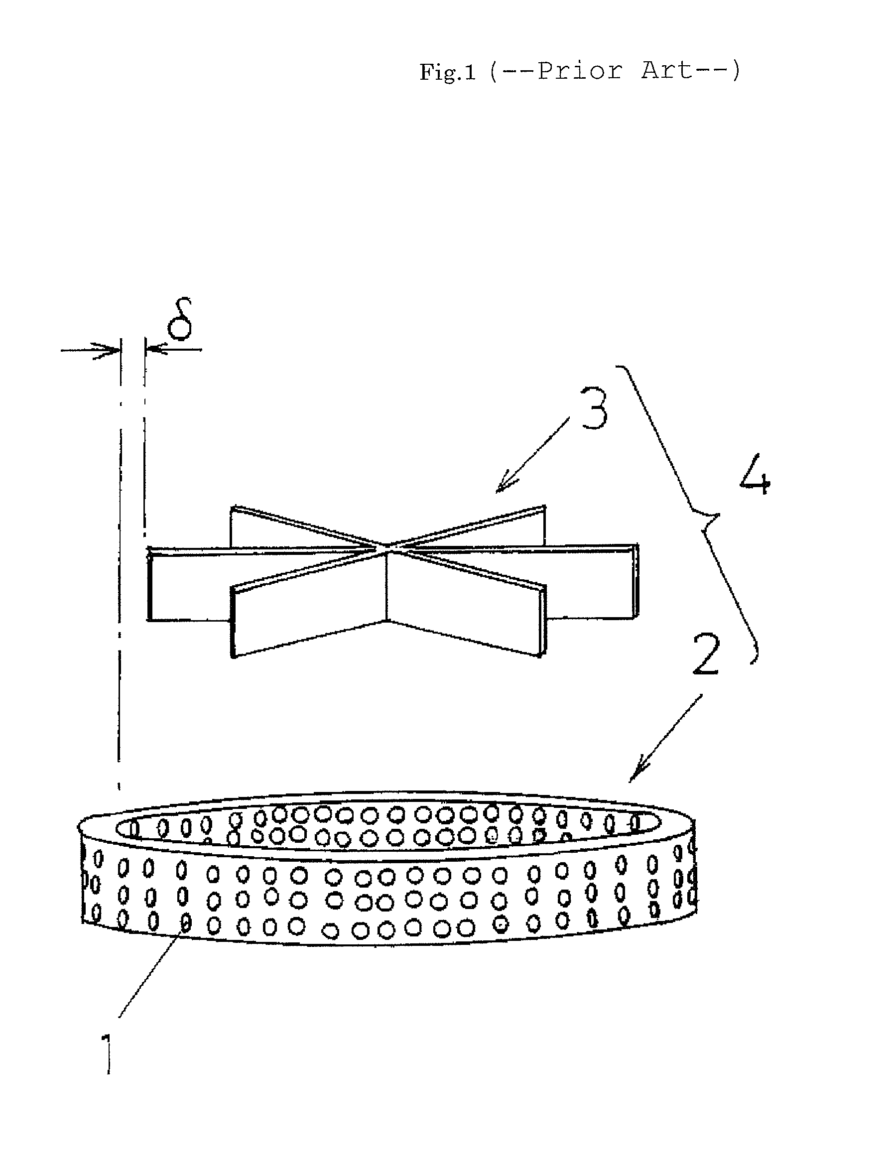
BACKGROUND[0001]1. Technical Field[0002]The present invention relates to the performance estimation and scale-up methods for the mixer of the so-called rotor-stator type, and more specifically to the mixer that includes a stator having a plurality of openings (holes) and a rotor that is disposed on the inner side of the stator and spaced by a predetermined gap away from the stator.[0003]2. Background[0004]As shown in FIG. 1, it is general that the mixer of the so-called rotor-stator type comprises a mixer unit 4 that includes a stator 2 having a plurality of openings (holes) 1 and a rotor 3 disposed on the inner side of the stator 2 and spaced by a particular gap δ from the stator 2. Such mixer of the rotor-stator type is provided for subjecting the fluid or liquid being processed to the emulsification, dispersion, particle size breakup, mixing or any other similar process, by taking advantage of the fact that a high shear stress may be produced in the neighborhood of the gap betwee...

Claims


Application Information

Patent Timeline
Patent Type & Authority Patents(United States)
IPC IPC(8): B01F5/16B01F5/10G01M13/00B01F7/16B01F25/64
CPCG01M13/00B01F5/104B01F5/165B01F7/164B01F2215/0404B01F2215/0409B01F25/52B01F27/812B01F25/642
Inventor KAMIYA, TETSU
Owner MEIJI CO LTD
Learn More