Variable optical filter and a wavelength-selective sensor based thereon

a variable optical filter and sensor technology, applied in the field of optical filters, can solve the problems of thin, narrowband transmission peak, weak out-of-band rejection, low-stress variable optical filter having simultaneously a low optical loss, etc., and achieve the effect of reducing the trade-off between thickness and optical performan

Active Publication Date: 2016-02-16
VIAVI SOLUTIONS INC
View PDF14 Cites 10 Cited by
  • Summary
  • Abstract
  • Description
  • Claims
  • Application Information

AI Technical Summary

Benefits of technology

[0010]It is a goal of the invention to alleviate the tradeoff between thickness and optical performance of a variable optical filter.
[0011]The inventors have realized that key optical requirements for materials in blocking and bandpass regions of a variable optical filter differ from each other in the following manner. In the blocking region, high index contrast is a key requirement. The high index contrast allows one to reduce the number of layers and increase the blocking efficiency. In the bandpass region, low loss is more important than the high index contrast, because light undergoes multiple reflections in that region, traversing the layers of the bandpass region many more times than in the blocking layer. Therefore, providing low-loss, but comparatively low-index material combinations in the bandpass region, together with high index contrast, but comparatively lossy material combinations in the blocking region, can result in a thin, low-stress variable optical filter having simultaneously a low optical loss, a narrowband transmission peak, and strong out-of-band rejection.
[0016]Advantageously, the bandpass filter further includes at least one fifth layer comprising the fourth material and disposed in an area of a local minimum of a standing optical wave inside the bandpass filter, whereby a blocking wavelength region of the bandpass filter is broadened, and a thickness of the bandpass filter is reduced.
[0019]Preferably, the array of photodetectors comprises a substrate for the optical filter. The array of photodetectors is provided, and the first to fifth layers are deposited directly onto the array, so as to form the bandpass and blocking filters, respectively, supported by the array. Among advantages of depositing the optical filter directly onto the photodetector array are increased spectral resolution due to light not having to propagate through a separate bulk substrate, reduced light leakage between neighboring photodetectors, and improved reliability. The optical filter can also be manufactured separately and affixed directly to the array, e.g. bonded with an optical epoxy.

Problems solved by technology

Therefore, providing low-loss, but comparatively low-index material combinations in the bandpass region, together with high index contrast, but comparatively lossy material combinations in the blocking region, can result in a thin, low-stress variable optical filter having simultaneously a low optical loss, a narrowband transmission peak, and strong out-of-band rejection.

Method used


Image

  • Variable optical filter and a wavelength-selective sensor based thereon
  • Variable optical filter and a wavelength-selective sensor based thereon
  • Variable optical filter and a wavelength-selective sensor based thereon

Examples


Embodiment Construction

[0052]While the present teachings are described in conjunction with various embodiments and examples, it is not intended that the present teachings be limited to such embodiments. On the contrary, the present teachings encompass various alternatives, modifications and equivalents, as will be appreciated by those of skill in the art.

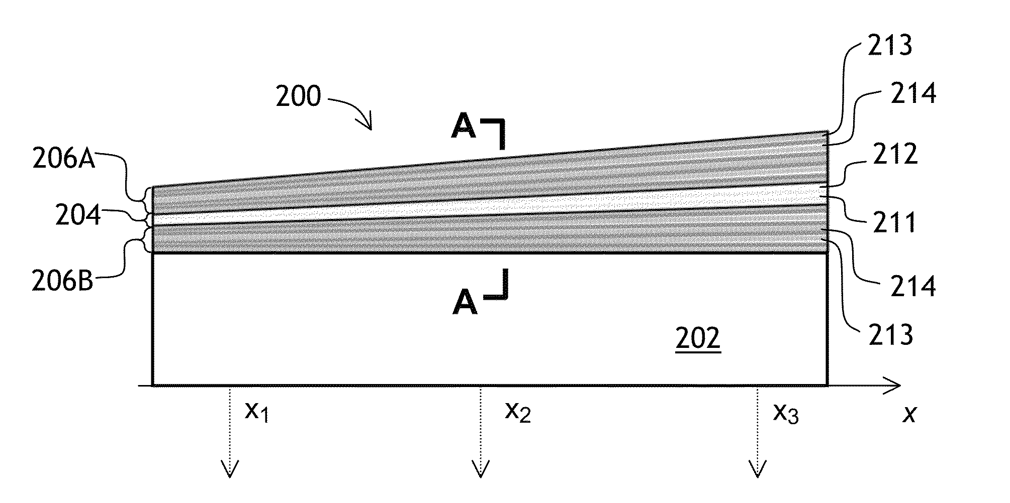
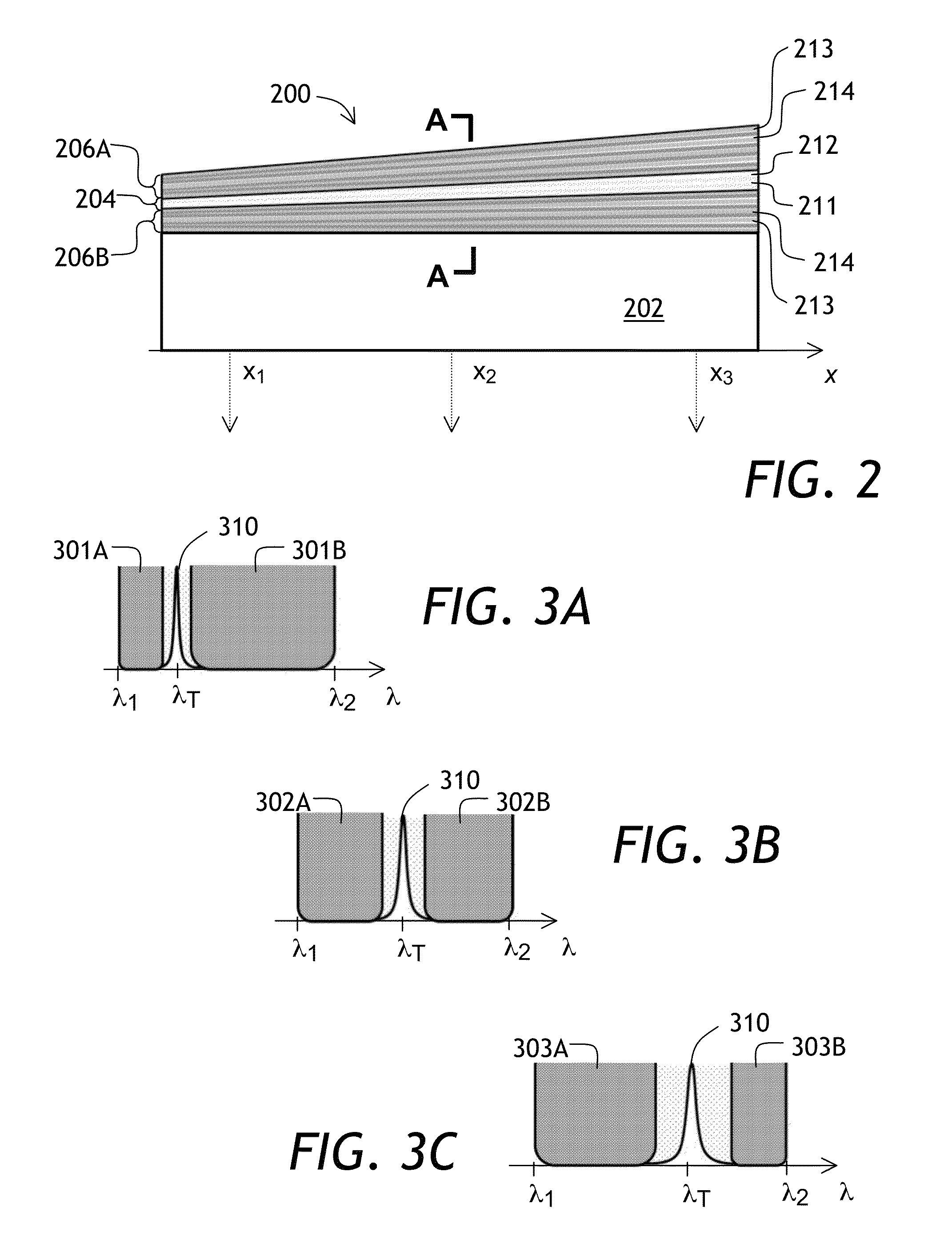
[0053]Referring to FIG. 2 and FIGS. 3A, 3B, and 3C, an optical filter 200 (FIG. 2) has a narrow passband 310 (FIGS. 3A to 3C) at a laterally variable transmission wavelength λT within a wavelength range between λ1 and λ2. The transmission wavelength λT is variable in a direction x shown in FIG. 2. The optical filter 200 can be disposed on a transparent substrate 202. The variable optical filter 200 includes a bandpass filter 204 and blocking filters 206A, 206B disposed over the substrate 202. The bandpass filter 204 comprises a stack of alternating first 211 and second 212 layers including first and second materials, respectively. The first 211 and second...


PUM


Abstract

A variable optical filter is disclosed including a bandpass filter and a blocking filter. The bandpass filter includes a stack of alternating first and second layers, and the blocking filter includes a stack of alternating third and fourth layers. The first, second and fourth materials each comprise different materials, so that a refractive index of the first material is smaller than a refractive index of the second material, which is smaller than a refractive index of the fourth material; while an absorption coefficient of the second material is smaller than an absorption coefficient of the fourth material. The materials can be selected to ensure high index contrast in the blocking filter and low optical losses in the bandpass filter. The first to fourth layers can be deposited directly on a photodetector array.

Description

CROSS-REFERENCE TO RELATED APPLICATIONS[0001]The present invention claims priority from U.S. Patent Application No. 61 / 757,846 filed Jan. 29, 2013, which is incorporated herein by reference.TECHNICAL FIELD[0002]The present invention relates to optical filters, and in particular to optical filters having spatially varying spectral characteristics.BACKGROUND OF THE INVENTION[0003]A spatially variable optical filter has a transmission wavelength varying in a transverse direction across the filter. A compact optical spectrometer can be constructed by attaching a photodetector array to a spatially variable optical filter. A filter having the transmission wavelength varying linearly with distance in a transverse direction across the filter is called a linearly variable filter (LVF). Linear variation of the transmission wavelength with distance is convenient, although not necessary. Optical spectra obtained using an LVF and a constant-pitch photodetector array have a constant wavelength st...

Claims


Application Information

Patent Timeline
Patent Type & Authority Patents(United States)
IPC IPC(8): G02B5/28H01L27/146
CPCG02B5/288G02B5/281H01L27/14621H01L27/14685G01J3/26G01J2003/1226G01J2003/1234G01J2003/1239G01J3/0259H01L27/1463H01L27/14643H01L27/14623H01L27/14634
Inventor HENDRIX, KAREN DENISEHULSE, CHARLES A.BRADLEY, RICHARD A.KUNA, JEFFREY JAMES
Owner VIAVI SOLUTIONS INC
Why Eureka
Try Eureka